2 Characteristics of ZigBee Technology ZigBee wireless technology features low power consumption, low cost, low data rate, short distance, and high communication reliability. Its network topology mainly supports three types of self-organizing wireless networks, namely, Star, Mesh, and Cluster Tree. Especially, the network topology has a strong network robustness. And system reliability. This makes ZigBee technology play a huge role in wireless meter reading systems with low power consumption, low cost, low data rate, and high reliability.
3 Design of ZigBee Wireless Module The ZigBee wireless module designed in this paper adopts rail-mounted installation mode, which can be easily installed on the 35mm standard rail. This allows the module to be flexibly installed in various types of distribution boxes and distribution cabinets. The appearance of the side view is shown in Figure 1. The technical specifications of the ZigBee wireless module are shown in Table 1.
Table 1 Technical Specifications of the ZigBee Wireless Module
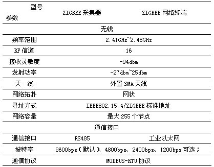
ZigBee wireless modules are divided into two types, among which the ZigBee signal-to-RS485 signal module is called the ZigBee acquisition module; and the ZigBee signal-to-Ethernet signal module is called the ZigBee network terminal, which is the initiator of the entire ZigBee network, ie ZigBee. The central node in the network.
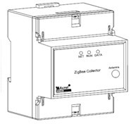
Figure 1 ZigBee module side view
3.1 Hardware Design The ZigBee wireless communication module is mainly composed of a switching power supply section, a ZigBee wireless transmission section, and an interface conversion section, and its functional block diagram is shown in FIG.
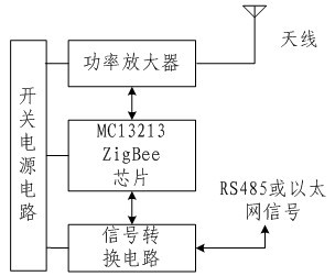
Figure 2 ZigBee communication module
The main part of the switching power supply circuit adopts the US company TOP221Y (TOPSwitch) of PI company, uses the flyback type power conversion circuit, converts the alternating current power into the DC power that we need; The wireless transmission part mainly uses the MC13213 chip, it is the freescale second generation ZigBee chip, Internal MCU chip and wireless transceiver, its schematic diagram shown in Figure 3; power amplifier using SKY65336, it can support up to 20dbm power amplification, the schematic diagram shown in Figure 4; signal conversion circuit sub-RS485 conversion Circuit and Ethernet conversion circuit, in which the Ethernet part uses Zhou Ligong's IPORT Ethernet module.
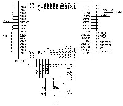
Figure 3 MC13213 schematic
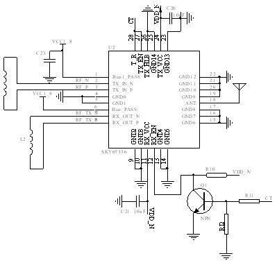
Figure 4 SKY65336 schematic
3.2 Software Design Figure 5 shows the flow chart for the ZigBee module network establishment. The entire ZigBee network is initiated by the central node (ie the ZigBee network terminal module). After the network is successfully established, it is on the same network frequency band. And a ZigBee acquisition module with the same network ID as ZigBee can automatically join this ZigBee network and each ZigBee acquisition module gets its own separate network address. At this point, the entire ZigBee network is established successfully and data transmission and reception can be prepared. ZigBee network terminals transmit data through broadcast.
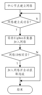
Figure 5 ZigBee module network establishment flow chart
Figure 6 shows the flow chart for data transmission of the ZigBee acquisition module. First, the ZigBee acquisition module receives data from the ZigBee network terminal module. Then it is judged whether it is the data passed to itself, if it is its own data, the relevant reply data is uploaded, and if not, the data from the ZigBee network terminal module is broadcasted according to the address in the routing table found by itself. After finishing all work, it enters sleep mode and waits for the next visit.
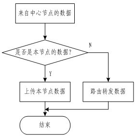
Figure 6 Data transmission flowchart of ZigBee acquisition module
ZigBee acquisition module and ZigBee network terminal all use transparent transmission, that is to directly convert Ethernet data into ZigBee signals, which will not add redundant data, only forward part of the data, automatically remove the frame header and frame trailer; RS485 signal conversion ZigBee The same principle applies to signals.
4 The application of ZigBee energy management system is shown in Fig. 7 as ZigBee energy management system. The telecommunication network of this article adopts industrial Ethernet network. The communication protocol of the electric meter in the network adopts MODBUS-RTU protocol. In the whole system, the monitoring host transfers the MODBUS-RTU command data to the ZigBee network center node via Ethernet according to the TCP/IP protocol. The network center node then transmits the command data frame to the broadcast through a single-to-multipoint communication mode. Each ZigBee collector in the ZigBee wireless network is sent to each meter on the 485 bus through the ZigBee collector. If the address of the meter matches the address involved in the command frame, the corresponding data reply will be made and the original route will be restored. Return to monitoring host.
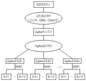
Figure 7 ZigBee power management system
The entire system can monitor the energy measurement of each sub-item across the entire plant area or the entire building, such as the power consumption of a street light in a plant, the power consumption of each office, the power consumption of each production line, etc., and can also be reported. Analyze the percentage of total energy consumption of each sub-item of the plant over a period of time, so that the factory can understand the energy consumption of each sub-item during this period of time to formulate a future energy management plan, which has reached the energy-saving reduction. The effect of consumption.
At present, the entire system is implemented in a manufacturing enterprise in Jiangyin. According to the principle of sub-item measurement, the incoming and outgoing lines of each road in the plant area are measured separately. Figure 8 is the power distribution diagram of the plant. The entire system is for all incoming lines. The loop is monitored and all ZigBee acquisition modules are used for data acquisition monitoring, including parameters such as current, voltage, and electrical energy, as well as some simple switching control. The system also monitors a number of branches, such as production lines, office buildings, air conditioners, etc., to perform all-round monitoring. This facilitates factories to understand various data in order to formulate more detailed energy-saving solutions.
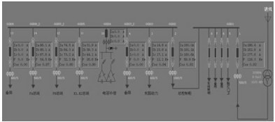
Figure 8 Plant distribution
At present, there are 21 wireless modules used throughout the ZigBee radio energy management system, including 82 blocks for various types of identification. Figure 9 shows the communication diagram in the ZigBee radio energy management system. It lists all the meters included in the entire system. Among them, the 14 tables of the power distribution room are connected to a ZigBee acquisition module through the 485 bus for wireless communication. Because each air-conditioning outlet is relatively decentralized, each adopts a ZigBee acquisition module, and so on. Specifically, depending on the discrete conditions of the meter, the 485 bus is used to connect one module and the other is connected to a separate module. In this way, it is more flexible and reduces the difficulty of wiring.
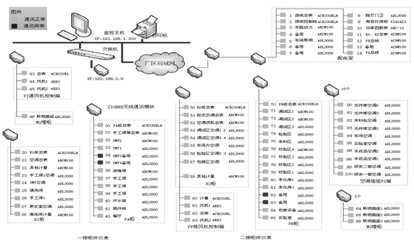
Figure 9 ZigBee radio energy management system communication diagram
The entire system is operating well and has been on site for a while. Figure 10 shows the trend of the main line current over a period of time. It reflects the current conditions of the plant in real time and reflects the load of the entire plant.
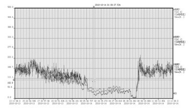
Figure 10 Main line current trend over time
Figure 11 shows the specific values ​​of the parameters of the incoming circuit in a certain period of time. It records in detail the three-phase voltage, current, active energy, non-functional power, power factor and frequency parameters of the incoming circuit. The summation of the electrical energy of each circuit in the entire plant area is shown in Figure 12. It records the power consumption of each circuit in a period of time, including the total power and branch power of each circuit.
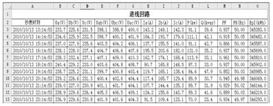
Figure 11 Parameters of the incoming line in a period of time
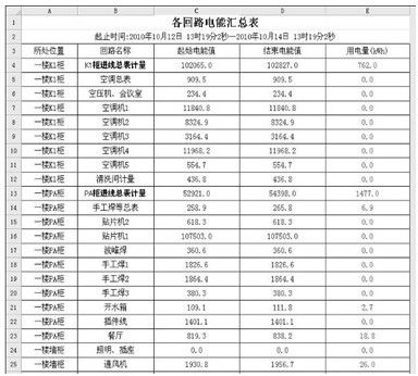
Figure 12 Energy summary of each loop
5 Conclusion With the rapid development of wireless communication and ZigBee technology, ZigBee-based power management systems will gradually get people's attention. ZigBee can solve the problems of difficult wiring, high cost, difficulty in maintenance and upgrade, etc., and the networking flexibility is very high. The application prospect in the power management system is very extensive, and it also has a wide range in the smart grid field. Application prospects.
The ZigBee wireless module introduced in this article has been successfully applied in the ZigBee radio energy system. The entire system has well monitored the incoming circuit of each circuit in the plant area and can truly reflect the load situation of the plant area. It will be energy saving and emission reduction. Make due contributions. In order to make the ZigBee radio energy management system better play its advantages, it is necessary to continuously optimize the hardware and software equipment in the system.
The article comes from: "Electric Drive Automation", Issue 3, 2011.
references:
[1] Wang Quanping, Wang Li. Communications World, 2003 (4).
[2] Jiang Xiubo. ZigBee technology and its application. Low-voltage electrical appliances, 2005 (7).
[3] Chang Meng, Yang Xiaolin, Liu Wei. ZigBee technology and its application in smart grid. Building Electrical, 2010 (4).
[4] Lü Zhenting, Cao Jian. Application of ZigBee technology in online monitoring system of power equipment. Electronic Measurement Technology, 2008, 31 (2): 191-194
[5] Hu Pingping, Wang Dongxing, Wang Jingjie. Application of ModBus Protocol in Wireless Monitoring System. Computer Engineering and Applications, 2005, 41(17): 211-214.
For more information, please contact us!
Company: Shanghai Ankerui Electric Co., Ltd. Address: No. 253 Yulu Road, Madong Industrial Park, Jiading, Shanghai Contact: Xia Liping Telephone
Q Q
mailbox:
Zip code: 201801