In this paper, embedded S3C2410 is used as the core chip, and a high-speed, high-precision data processing system with certain processing capability is designed and implemented, and it is applied to real-time monitoring of water level and temperature in industrial process.
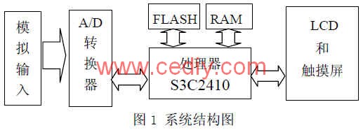
2. System overall design This design uses ARM9 as the core of S3C2410 as the core of data acquisition and processing, including the following four modules: signal acquisition, data storage, data display, data transmission. The analog signal is input to the S3C2410 processor on-chip A/D converter through the amplifying circuit, and the processed result is displayed on the LCD in the form of a dynamic waveform, and the display mode is controlled by the touch screen. At the same time, it is sent to the PC through the serial port, and the program written in VC++ on the PC performs subsequent processing such as display and storage of the data. The system structure is shown in Figure 1.
3. Hardware circuit design
The temperature and water level are measured using a transmitter. Taking the temperature transmitter as an example, the system uses the STY series integrated temperature transmitter of Beijing Saiyiling Technology Co., Ltd. Its measuring range is 0~150°C, and its output is one with the measured temperature. A linear current relationship of 4 to 20 mA constant current signal.
In order to meet the measurement requirements, a resistor is connected between the two output terminals of the temperature transmitter to convert the output current signal into a voltage signal. Considering that the input range of the S3C2410 internal A/D converter is 0-3.3v, Use a 165 Ω resistor. The circuit connection diagram is shown in Figure 2. 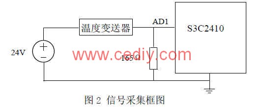
This article refers to the address: http://
It can be seen from Fig. 2 that the 4-20 mA current signal generated by the temperature transmitter is converted into a voltage signal of 0.66-3.3 V through the circuit conversion, and the voltage signal is transmitted to the A/D converter inside the S3C2410. The sampling temperature value can be calculated as follows. The sampled voltage value is UT, the unit is V, and the corresponding temperature is T, the unit is °C, then the value of T can be obtained by the formula (1): 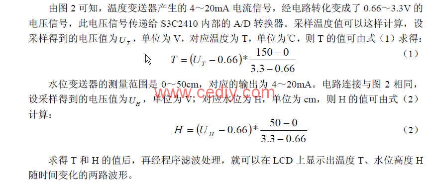
4. System software design software design is mainly uC/OS-II transplantation and task writing. uC/OS-II is a free, scalable, open source, compact, preemptive real-time multi-tasking embedded kernel, mainly for small and medium-sized embedded systems, with high execution efficiency, small footprint, and high portability. , real-time performance and scalability are strong [2].
In order to facilitate porting, most uC/OS-II code is written in ANSI C; however, it is still necessary to write some processor-related code in C and assembly language because uC/OS-II is reading. / When writing a processor register, it can only be implemented in assembly language. The processor-related code includes three files: OS_CPU.H, OS_CPU_A.ASM, and OS_CPU_C.C, so the main task of the migration is to modify these three files.
(1) There are a few points to note when modifying the code associated with the processor and compiler in OS_CPU.H [3]:
(a) Different processors have different word lengths. uC/OS-II does not use C int, short, long and other data types in order to ensure portability. Because these data types are compiler-dependent, Not portable.
(b) Modify the two macros OS_ENTER_CRITICAL() and OS_EXIT_CRITICAL(). uC/OS-II needs to disable the interrupt and then access the critical section of the code, and re-enable the interrupt after the access is completed. The function of OS_ENTER_CRITICAL() is the off interrupt, which is implemented on the S3C2410 by the INTS_OFF() function in OS_CPU_A.ASM. OS_EXIT_CRITICAL() is used to open interrupts, which is implemented by the INTS_ON() function in OS_CPU_A.ASM.
(c) OS_STK_GROWTH is used to define the stack growth mode. Setting 0 means the stack grows from bottom to top, and setting 1 means the stack grows from top to bottom. In this design, the stack is used to grow the S3C2410 processor from top to bottom, so it is set to 1. (d) OS_TASK_SW() is a task switching macro for switching from a low priority task to a high priority task. It encapsulates the task switching function OSCtxSw().
(2) Modify the OSTaskStkInit() function associated with the operating system in OS_CPU_C.C
OSTaskStkInit() is used for task stack initialization. OSTaskCreate() and OSTaskcreateExt() initialize the stack structure of the task by calling OSTaskStkInit(). Figure 3 shows the form of task stack initialization when OSTaskStkInit() is created.
(3) Write four processor-related functions in OS_CPU_A.ASM
OSStartHighRdy( ) is called by the OSStart( ) function in the program to start the task with the highest priority in the ready task. OSCtxSw() is a task-level task switching function that is implemented by executing a soft interrupt instruction or by executing a TPAR (trap) instruction depending on the processor. OSIntCtxSw() is an interrupt-level task switching function. By calling it, you can perform task switching in the ISR. OSTickISR() provides a periodic clock source for uC/OS-II to implement time delay and timeout functions.
5. The application task design system flow chart is shown in Figure 4. 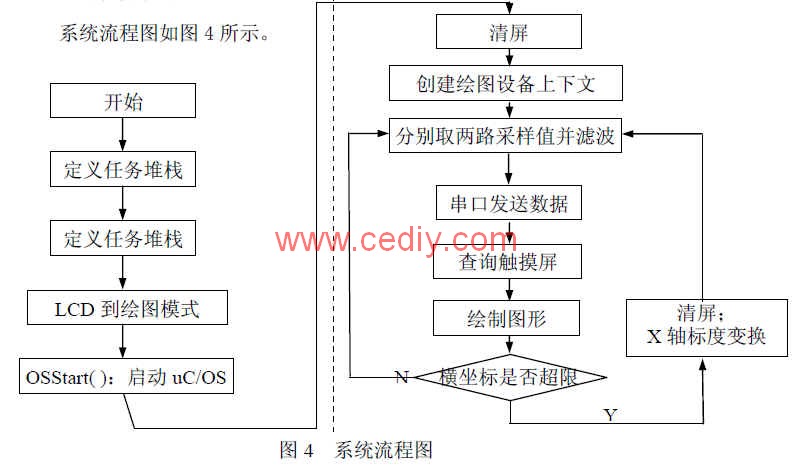
(1) Initializing the uC/OS-II system environment The functions performed in the left half of Figure 4 are to start the operating system and create two tasks, Main_Task and tch_Task. The right half is the main content of Main_Task() and tch_Task(), which is the focus of this design. The acquisition of the analog signal is done in Main_Task(), and the control of the display mode is done by tch_Task().
(2) Programming to achieve A/D conversion The acquisition of analog data is done in Main_Task( ) by calling the functions void init_ADdevice() and intGetADresult(int channel). A 10-bit digital quantity of the analog signal after A/D conversion, through equation (1)
(2) Convert it into actual data. 3.3 in the equation represents the upper limit of the analog quantity, 1023 is calculated by (2 10-1), and the calculated data is the actual analog value. The data is filtered and stored in two variables for the following part of the drawing program.
(3) Touch screen control program The idea of ​​this part of the program is: if there is a touch action, take the coordinate value of the contact to determine whether it belongs to the coordinate range of the control button displayed on the LCD, and if so, make the corresponding control adjustment, if not action. The subfunction returning the contact coordinates is TchScr_GetScrXY(int *x, int *y). In this design, three control buttons are defined that are used to convey control information.
(4) Drawing API functions
In the uC/OS-II system environment, drawing must be done using the drawing device context (DC). Drawing device context (DC) includes information related to drawing, such as drawing coordinates, brush color, brush width, and so on. In actual use, CreateDC() is used to create the drawing device context, and DestoryDC(pdc) is used to delete the drawing device context. These two statements should appear in pairs in the program. By using the functions LineTo(), TextOut(), Circle(), MoveTo(), etc., the sampled values ​​can be displayed on the LCD in real time.
The following two points are worth noting when drawing LCD:
(a) Use the LineTo( ) and MoveTo( ) functions repeatedly during LCD drawing, but be sure to pay attention to the resolution of the LCD before using this function. Only know the LCD resolution, you can know the range of the LCD's coordinate values, and get the correct setting results. The LCD resolution used in this design is 640*480. That is to say, the range of x values ​​of the initial coordinate system is (0 ≤ x ≤ 640), and the range of y values ​​(0 ≤ y ≤ 480).
(b) Since the LCD width is limited, when the abscissa x>LCDWidth, the waveform is out of the display range. The solution is to display the waveform drawn from left to right on the LCD. When drawing to the rightmost end of the LCD, after clearing the screen, draw the line from the left end of the LCD to the right again, and the value of the abscissa changes accordingly.
(5) Data display program on PC
In order to better record and analyze the data, we wrote the program on the PC with VC, which can save and process the data well, which provides favorable conditions for performance analysis and system failure recovery.
6. in conclusion
The uC/OS-II real-time operating system is an open source and proven software platform, while the ARM processor has powerful 32-bit RISC performance. Based on uC/OS-II and ARM, it can greatly reduce R&D tasks, improve R&D speed, and create conditions for designing data acquisition systems with excellent control performance in a short period of time. The data acquisition system of this paper has been successfully applied to the real-time measurement and control of temperature and water level in industrial applications, and achieved good results.
The author of this paper innovates: Abandoning the traditional single-chip data acquisition, using the portable uC/OS-II system with good portability, with the characteristics of simple development, good system stability and high reliability. This design can be easily ported to other data acquisition systems.
BBQ Grill,Fashion Barbecue Grill,Stainless Steel Grill,Smokeless BBQ Grill
Shaoxing Haoda Electrical Appliance Co.,Ltd , http://www.zjhaoda.com