Texas Instruments (TI)'s Level 3 electric/hybrid car battery charger uses digital power controllers, communication devices, high-performance drivers and interface devices. Level 3 chargers include AC/DC converters with PFC and DC/DC converters that generate DC voltage from AC. Its core device is a real-time C2000 series MCU.
Plug-in hybrid electric vehicles (PHEV) and battery electric vehicles (BEV) are two increasingly emerging technologies that use powerful motors and high-voltage battery packs as power and energy sources. Because the battery has a certain energy performance, PHEV and BEV must be supplemented periodically, usually by connecting to the grid. In doing so, some form of communication (PLC, wireless or RFID) may be used to manage charging activities and help authenticate the vehicle or owner for billing purposes. Level 3 charging will play an important role in the public charging field to reduce charging time and allow users to benefit more from the charging process.
The Level 3 charging system for cars includes an AC/DC converter to generate a DC voltage from an AC line. The electricity that is about to be charged will require power factor correction (PFC) to increase the power factor, so as to meet regional regulatory standards. At the center of the inverter is a real-time C2000 microcontroller. This controller is programmed to implement the required power management functions for the control loop, including AC/DC and DC/DC using PCF, to create the required elements for the battery. The C2000 controller includes advanced peripherals such as high-precision PWM output and ADC, which is designed to read the ADC and adjust the PWM in a single clock cycle to achieve real-time control.
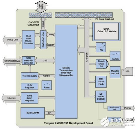
Figure 1 Block diagram of DK-LM3S9B96 development board
Since the C2000 manages power, the host controller is responsible for using the information provided by the communication module and the temperature sensed to drive direct communication with the on-board battery pack. The information required for the charging status will be transmitted to the power controller, and important charging diagnosis and battery status will be sent to the display of the Level 3 charging system.
For safety reasons, isolation is required between the processor and the power supply and voltage, and between the communication bus and the external environment. TI's digital isolators have logic input and output buffers separated by TI silicon dioxide (SiO2) isolation barriers, providing an isolation voltage of 4kV. When combined with isolated power supplies, these devices block high voltages, isolate ground voltages and prevent noise currents from entering the ground, affecting and destroying sensitive circuits. High-performance analog components can be used to provide important system functions, such as MOSFET drivers, sensor feedback, chip power, and communication transceivers.
Communication on the simple system can be controlled by a separate processor. More systems with complex displays and linear accounting/reporting functions like Level 3 charging systems may require a second controller. A low-frequency NarrowBand PLC (LF NB PLC) solution used provides a better configuration in terms of bandwidth, power and cost requirements. Operating in the narrowband domain (frequency up to 500kHz) ensures data integrity and reduces system costs. In this way, this standard will weigh the existing power line architecture and provide a cost-effective way to integrate intelligent monitoring and control new automotive systems. The data rate can vary from 1.2kbps to hundreds of kbps according to existing standards. TI's PLC software is provided in the plcSUITE resource library, and allows users to support several modulations and standards in one design. Developers can implement SFSK ICE61334, PRIME and G3 standards, and FlexOFDM standards in a single design to achieve customization of OFDM and have applicability to upcoming standards. In addition, wireless communication and/or RFID may need to be used as the second communication protocol and authentication and billing method.
The Stellaris LM3S2000 series, designed for controller area network (CAN) applications, expands the Stellaris series with Bosch CAN network technology (which is the gold standard for short-range industrial networks). Its launch sign is the first integration of CAN performance using the revolutionary ARM Cortex-M3 core. In addition, several LM3S2000 series MCUs are also edited in the StellarisWare software feature of the memory ROM.
TI penetrates all the advantages of 32-bit performance and ARM Cortex-M3 core microcontrollers into all aspects of the microcontroller's high field. For current 8-bit and 16-bit MCU users, the Stellaris series with Cortex-M3 core provides a diameter access path to powerful development tools, software, and industry knowledge. Those designers who will switch to Stellaris will benefit from a large number of tools, small code footprint and outstanding capabilities. And more importantly, designers can implement the ARM subsystem on the basis of confidence in the $1~1GHz compatible development roadmap. For current users of 32-bit MCUs, the Stellaris series provides products that use Cortex-M3 and Thumb-2 instruction sets. Through extremely fast response, Thumb-2 technology integrates 16-bit and 32-bit instructions to provide a good balance of code density and performance. Compared with 32-bit code, Thumb-2 reduces all memory by 26%, yet provides 25% higher performance. Texas Instruments Stellaris series microcontrollers are ARM Cortex-M3 core microcontrollers, which bring high-performance 32-bit computing to cost-sensitive embedded microcontroller applications. These pioneering products allow customers to achieve 32-bit performance at a price equivalent to previous 8-bit and 16-bit devices, all in a small-pin package.
LM3S2B93 microcontroller features
Main features of LM3S2B93 MCU:
• ARM Cortex-M3 processor core
– 80-MHz operating frequency: 100 DMIPS performance
– ARM Cortex SysTick timer
-Nested Moderate Interrupt Controller (NVIC)
• On-chip memory
–Up to 50 MHz 256 kB single-cycle flash memory; prefetch buffer improves performance above 50 MHz
– 96kB single loop SRAM
-Internal ROM with StellarisWare software
• Stellaris Peripheral Driver Database
• Stellaris boot loader
• Advanced Encryption Standard (AES) password usage table
• Cyclic Redundancy Check (CRC) error detection function
• External Peripheral Interface (EPI)
-8/16/32-bit dedicated flat bus for external peripherals
– Support SDRAM, SRAM/Flash, FPGAs, CPLDs
• Advanced serial integration
-Two CAN 2.0 A/B controllers
-Three UARTs with IrDA and ISO 7816 support (one UART with demodulator control and status)
-Two I2C modules
– Two synchronous serial interface modules (SSI)
-Integrated chip audio (I2S) module
•system integration
-Direct memory access controller (DMA)
-Including on-chip high-precision 16MHz oscillator system control and clock
-Four 32-bit timers (up to 8 16-bits)
– 8 capture compare PWM pins (CCP)
-Low-power battery pack sleep module
-Real-time clock in hibernation module
-Two watchdog timers
• A timer separate from the main oscillator
• A timer separated from the high-precision internal oscillator
-Up to 67 GPIO, depending on the specific configuration
• Highly flexible pin combination, allowing the use of GPIO or one of a variety of peripheral functions
• Independently configurable to 2mA, 4mA or 8mA drive performance
• Up to 4 GPIOs can have 18 mA current drive performance
• Advanced motion control
– Eight advanced PWM outputs, suitable for sports and energy applications
-Four fault outputs, which can promote low-latency shutdown
– Two integral encoder inputs (QEI)
•simulation
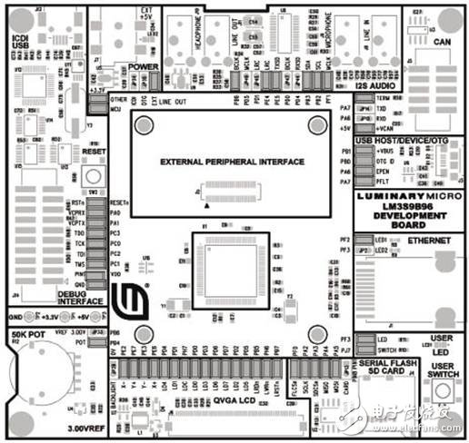
Figure 2 DK-LM3S9B96 development board PCB top-level component layout
– Two 10-bit analog-to-digital converters (ADC) with 16 analog input channels and a sampling rate of millions of samples per second
-Three analog comparators
–16 digital comparators
--On-chip voltage regulator
• JTAG and ARM serial wire debug (SWD)
• 100-pin LQFP package
• 108-ball BGA package
•Industrial (-40℃~85℃) temperature range
The LM3S2B93 microcontroller is oriented to industrial applications, including remote monitoring, electronic point-of-sale equipment, test and measurement equipment, network equipment and switches, factory automation, HVAC and building control, game consoles, motion control, transmission, fire protection and security.
For applications that require greater power conversion, the LM3S2B93 microcontroller has a sleep module for the battery, which can effectively reduce the power of the LM3S2B93 during inactivity to a low-power state. Utilizing power-on/power-down sequencer, continuous time counter (RTC), a pair of matching registers, an APB interface for system bus and dedicated non-volatile memory, the hibernation module makes the LM3S2B93 microcontroller fully suitable for battery applications .
In addition, many of the advantages of ARM provided by the LM3S2B93 microcontroller are widely applicable to development tools, system-on-chip (SoC) architecture IP applications and large user communities.
In addition, the microcontroller uses ARM's Thumb-compatible Thumb-2 instruction set to reduce memory requirements and thereby reduce costs. The LM3S2B93 microcontroller is compatible with all products in the extended Stellaris series; it provides flexibility to meet customers' high-precision requirements.
The components are as follows:
• R1 reset pull-up resistor
• C1 reset input filter capacitor
• C3 LDO regulator filter capacitor
• C2, C4-C6, C11 VDD decoupling capacitor
• C7, C18 VDDC decoupling capacitor
• C12-C17 crystal load capacitor
• Y1 Ethernet crystal
• Y2 main oscillator crystal
• Y3 sleep module crystal
• R3 Ethernet RBIAS resistor
• R2 sleep oscillator resistor
• R5 USB RBIAS
• R4 MDIO pull-up resistor
Stellaris LM3S9B96 Development Board
The Stellaris LM3S9B96 development board provides a platform for developing systems with the performance of the LM3S9B96 ARM Cortex-M3 core microcontroller.
LM3S9B96 is a member of the Stellaris Tempest-class microcontroller family. The performance of Stellaris Tempest-class devices includes 80 MHz clock speed, an external peripheral interface (EPI) and audio I2S interface. In addition to the new hardware to support these features, the DK-LM3S9B96 board includes the rich peripheral set that the Stellaris board has.
The development board includes an on-board circuit debug interface (ICDI) that supports both JTAG and SWD debugging. A standard ARM 20-pin debug header supports an array of debug solutions.
The Stellaris LM3S9B96 development kit accelerates the development of Tempest-class microcontrollers. The kit also includes more sample applications and complete resource codes.
Main features of Stellaris LM3S9B96 development board:
•Easy setup-USB cable provides debugging, communication and power
• Flexible development platform with multiple peripherals
• Color LCD picture display
– TFT LCD module with a resolution of 320×240
--Resistive touch interface
• 80 MHz LM3S9B96 microcontroller with 256k Flash, 96k SRAM, and integrated MAC+PHY, USB OTG and CAN communication
– 8 MB SDRAM (plug-in EPI option board)
– EPI break-out board (optional plug-in board)
• 1 MB serial flash memory
• High-precision 3.00 V reference voltage
• SAFERTOS operating system in the microcontroller ROM
• I2S stereo audio codec
--Linear input/output
--Headphone output
• Controller Area Network (CAN) interface
• 10/100 Ethernet
• USB On-The-Go (OTG) connector
• Device, host and OTG mode
•User LEDs and buttons
• Thumbwheel divider (can be used for menu navigation)
• MicroSD card slot
• Support a wide range of debugging options
-Integrated in-circuit debug interface (ICDI)
-Fully support JTAG, SWD and SWO
-Standard ARM 20-pin JTAG debug connector
• USB physical COM port
• Jumper shunt can easily redistribute I/O resources
• Use tools that support Keil RealView Microcontroller Development Kit (MDK-ARM), IAR embedded work platform, coding resources GCC development tools, red code technology development tools or TI code compiler Studio IDE
• Supported by StellarisWare software, including image library, USB library and peripheral drive library.
• An optional expansion board that works with the external peripheral interface (EPI) DK-LM3S9B96 development board to extend the performance of this development platform (sold separately)
– Stellaris flash memory and SRAM memory expansion board (DK-LM3S9B96-FS8) (sold separately)
• Provide flash memory, SRAM and LCD interface to improve performance
– Stellaris FPGA expansion board (DK-LM3S9B96-FPGA) (sold separately)
• Provides machine-to-machine (M2M), high-bandwidth, parallel interface performance of Stellaris microcontroller
• Enable users to control and display the video of the FPGA expansion board on the 3.5" touch screen of the DK-LM3S9B96 development board. Learn more about DK-LM3S9B96-FPGA.
– Stellaris EM2 expansion board (DK-LM3S9B96-EM2)
• Provides transmission between the Stellaris external peripheral interface (EPI) connector and the RF evaluation module (EM) connector
• The low-power RF and RF ID evaluation modules on the Stellaris DK-LM3S9B96 platform can be used to achieve wireless application development
Patent Vape,E-Cigarette Vape Pens,E-Cigarette Vaporizer Pen,Disposable Vape Puff Bar
Guangzhou Yunge Tianhong Electronic Technology Co., Ltd , https://www.e-cigarettesfactory.com