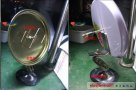
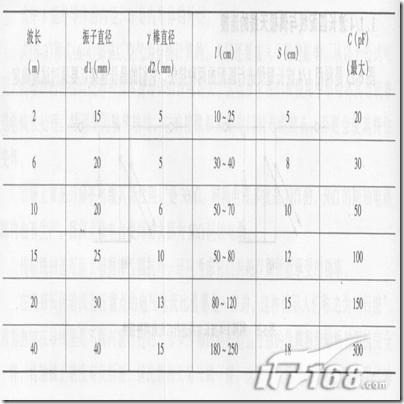
The distance between the feeding ends of the active elements of the antenna is about 5-10 mm. I did not add a "balanced-unbalanced" converter, and the 50-ohm coaxial cable was directly connected to the active vibrator. The horizontal oscillator impedance is about 73 ohms. The more passive elements of a Yagi antenna, the lower the input impedance will be. The 5EL 70cm band YAGI antenna made by 4RAE, the active vibrator is a folded vibrator (impedance 300 ohm), but the coaxial cable is directly connected to the feed end of the folded vibrator through a 1: 1 "balance-unbalance converter" . Made of 5EL YAGI, the effect is good after use. In June this year, with the BG4RAE in this band QSO, the signal 59.4 "balance-unbalance" converter is a kind of so-called sleeve-type "balance-unbalance" converter. In principle, a dipole antenna or a folded dipole antenna, when the feeder is a coaxial cable, a converter should be added to complete the unbalanced-balanced conversion of the feed, but the picture is simple when produced under amateur conditions. Can be used. For the structure of 4RAE's sleeve-type "balance-unbalance" converter, please refer to Figure 3. The YAGI antenna I made, the distance between the elements is equidistant, and the 4RAE is not equidistant. The same is the 5EL YAGI antenna, the total length is shorter than the size I give. From the analysis in the textbook, we know that the size of a YAGI is not unique. If the distance between the directors is longer, the directionality of the antenna will be stronger, but if the distance is too long, the gain will decrease and the antenna size will increase at the same time. Under normal circumstances, the distance between each oscillator is about 0.2 wavelength is more appropriate. I remember that there was a TV commercial that meant that it should be easy to use and beautiful. Finally, paint the finished antenna with green paint, just a little yellowish self-painting on hand, spray it randomly, and "wear" it with a camouflage suit. Figure 4 is an assembly diagram. 

Follow WeChat

Download Audiophile APP

Follow the audiophile class
related suggestion
The story made by the engineer: The whole process of Niuren's homemade WIFI Shuangling antenna. This production refers to the drawings collected on the Internet. It is said that there is a gain of about 11DB ...

This production refers to the drawings collected online. It is said that there is a gain of about 11DB, and the test is indeed true after completion.
Remote key matching method for some vehicle models 1. Jetta remote control matching 1. Setting of the first remote key. (1) The remote key to be set will be clicked ...
The origin of 50 / 75Ω matching • This is derived from the high power transmission capacity and attenuation characteristics of the coaxial cable • ...
The output matching network design of MAX1472 ASK transmitter MAX1472 is a phase-locked loop transmitter with crystal as reference clock.
What is gamma (γ) matching? Gamma (γ) matching is actually a half of T-shaped matching, suitable for connecting with 50Ω coaxial cable, which is a very convenient ...
MAX1470 circuit adjustment and antenna matching How to Tune and Antenna Match ...
Impedance mismatch distribution circuit The high-speed circuit has a relatively shorter wavelength due to the increase in operating frequency. When the wavelength is close to the length of the line to a similar order of magnitude
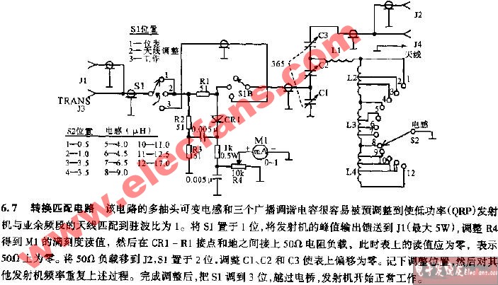
Conversion matching circuit diagram
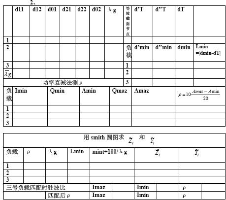
Impedance measurement and matching technology 1. Experimental purpose 1. Master the principles and methods of measuring impedance with a measuring line. 2. Learn matching techniques. 3. Familiar with Smi ...
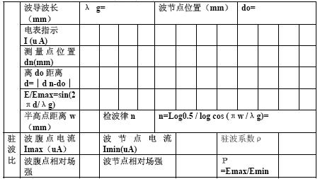
Crystal calibration and matching load standing wave ratio measurement 1. The purpose of the experiment 1. To be more familiar with the use of the three-centimeter microwave test system and the measurement line 2. To master ...
What is gamma Y matching, what does gamma (Y) matching mean? Gamma (γ) matching is actually a half of T-shaped matching, suitable for coaxial with 50Ω ...

Reduction of matching loss through active combination of output impedances: in high-speed transmission line applications
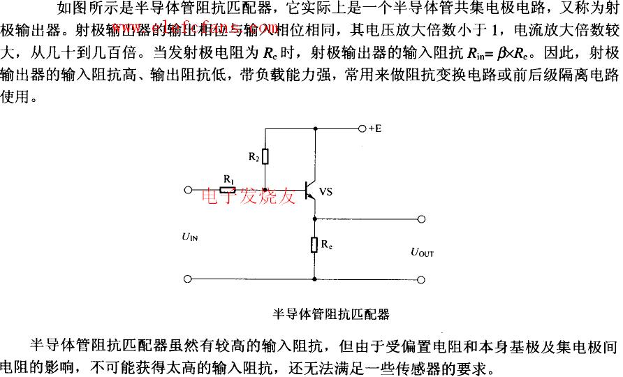
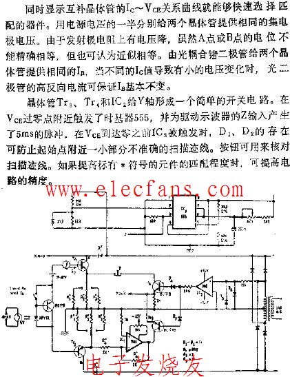
As shown in the figure is a semiconductor impedance matcher, which is actually a semiconductor common collector circuit, also known as an emitter output device.
Matching of complementary transistors
Yagi antenna is a kind of directional antenna, made by ...
![[Photo] FM three-unit Yagi antenna production](http://i.bosscdn.com/blog/20/06/41/5211012552.jpg)
'+ data.data.username +' '; dom + ='
Edge Sealing Machine,Automatic Sealing Machine,Heat Sealing Machine,Automatic Edge Sealing Machine
Dongguan Yuantong Technology Co., Ltd. , https://www.ytbagmachine.com