Overview Electrocardiogram (ECG or EKG) is used to measure the myocardial electrical signal that changes with time, and the measurement results are graphically displayed. The application range of ECG ranges from simple heart rate monitoring to special heart condition diagnosis. In any application, the ECG test principle is the same, but the design details and requirements for electronic components vary widely, from portable devices that cost less than $ 200 to desktop devices that exceed $ 5000 and are the size of a fax machine. In some applications, ECG is even embedded in other instruments, such as patient monitors, automatic external defibrillators (AED), etc.
All ECGs collect ECG signals through electrodes connected to specific parts of the body. The amplitude of the ECG signals generated by the body is only a few millivolts. Through the electrodes connected to specific positions of the body, ECG activities can be observed from different angles The position can be displayed and printed as an output channel of ECG. Each channel represents the differential voltage between two electrodes or the difference between the average voltage of a certain electrode and several electrodes. Different combinations between electrodes can show the number of specific electrodes. More channels. These channels are generally called "leads" (or "channels"), and a 12-lead ECG device has 12 independent graphical display channels. Depending on the application, the number of leads can be selected from 1 to 12. The problem is that the wire connecting the electrodes is sometimes called a lead, which is confusing, because the 12-lead (12-channel) ECG only requires 10 electrodes (10 wires), so carefully judge the "lead United ".
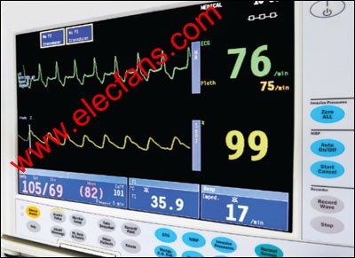
ECG and blood oxygen readings displayed on the patient monitor
In addition to biological signals, most ECGs will also detect two artificial signals, of which the implantable cardiac pacemaker (referred to as the "pacing" signal for short) is the most important signal. The pacing signal time is quite short, from tens of microseconds to a few milliseconds, and the amplitude from a few millivolts to nearly 1 volt. Generally, ECG must also detect the presence of pacing signals to prevent interference with other ECG signals.
The second type of artificial signal is used to detect "lead drop", that is, poor contact of the electrode. Many ECGs need to issue an alarm indication when the electrode is in poor contact. To this end, the ECG device generates a signal for measuring the impedance between the electrode and the human body, thereby detecting whether there is lead loss. The measurement signal can be AC ​​or DC, or both. Some ECGs can also detect the respiratory rate by analyzing impedance when detecting the state of lead detachment. The lead-off state should be continuously detected, and it cannot prevent accurate measurement of the ECG signal.
ECG overall functional block diagram. For Maxim ’s recommended solutions for ECG design, please visit www.maxim-ic.com/ECG.
Features If the ECG is divided into an analog front end (AFE) that digitally converts the signal and the "rest" that will analyze, display, store, and transmit data, it is easier to understand the requirements of the electrocardiograph for electronic components. AFE usually has the same basic requirements, the difference is the number of leads, signal fidelity, interference suppression capabilities, etc. Depending on the specific functional requirements, the rest of the system varies greatly. Typical functions include: display, printing hardware copy, wireless (RF) connection, and battery charging.
One of the most significant characteristics of the number of leads is the number of leads. Some ECGs have only one lead, while others have up to 12 leads. The most commonly used 12-lead ECG requires 10 electrodes, 9 of which are used to collect electrical signals. The 10th electrode is connected to the right leg (RL) and driven by the ECG circuit to reduce the common-mode voltage. The nine input electrodes are: one electrode for each of the left arm (LA), right arm (RA), and left leg (LL), and six electrodes (V1 to V6) in the anterior heart (chest) area. Each lead or cardiogram shows the voltage difference between one electrode and another electrode or a group of electrodes. If the electrodes are grouped, the average voltage is taken. The 6 leads from the three electrodes RA, LA, and LL are averaged and used as one side of the differential pair, and V1 to V6 are used as the other side of the six differential pairs. There are three leads derived from the difference between the mean values ​​of RA, LA, and LL and the other two electrodes. The remaining three leads are the results of measuring RA, LA, and LL as independent differential pairs. The six leads based on RA, LA, and LL contain similar information, but are displayed in different ways. Because the information is redundant, there is no need to measure all 6 leads. Some channel data can be analyzed and calculated by DSP on other channel data.
What is described here is the most commonly used 12-lead system, but it is not the only solution. In addition, the 12-lead ECG can also be used as a 5-lead, 3-lead, or 1-lead system. The key is that when more than one lead is needed, a switch array and averaging circuit are required.
Analog Front End (AFE) The main function of AFE is to digitize the ECG signal. Due to the need to suppress strong interference such as RF signal source, pacing signal, lead drop detection signal, power frequency common mode signal and other body signals and electronic noise , The process is very complicated. In addition, millivolt-level ECG signals may be superimposed on the DC offset voltage of hundreds of millivolts, and the common-mode voltage between the channels may exceed 1 volt. The electrodes connected to the patient's body must not create a risk of electric shock or interfere with other medical instruments connected to the patient. The effective frequency range of ECG is somewhat related to the application, and is usually between 0.05 Hz and 100 Hz.
The second function of AFE is to be able to detect pacing signals, lead shedding, respiratory rate and patient impedance. The detection works on several channels simultaneously or almost simultaneously. In addition, when defibrillating, most ECG devices need to recover quickly, but because the defibrillation causes saturation of the front-end circuit and charging capacitor, these capacitive coupling circuits will extend the recovery time.
AFE function in various ECG applications
A = always, U = usual, S = sometimes, N = never
AFE architecture AFE architecture has a great impact on system performance. The enhanced architecture described below, due to the use of high-precision, high-speed ADC (analog-to-digital converter), provides high fidelity in a wide frequency range. Instead of capacitive coupling, the DAC (digital-to-analog converter) is used as the RL driver, allowing the AFE to recover quickly from defibrillation or radio frequency interference. The digital pacing signal allows analysis of pacing data, thereby reducing false pacing indications and even detecting defects in pacemakers or connecting parts. On the other hand, it is also necessary to consider that the enhanced system requires expensive components and consumes a lot of power. In contrast, the simplified AFE is cheap, has a longer battery life, and has very little difference in other characteristics.
Enhanced AFE and DSP AFE: A high-performance ADC is required to meet the ECG test requirements. It can simultaneously quantize 9 electrode signals, and the noise-free accuracy can reach 20 bits at a sampling rate of 200ksps. Then use a digital signal processor (DSP) to calculate each lead signal, isolate the pacing signal, lead off signal and breathing signal, and filter out the interference frequency signal. The DSP also calculates the signal strength required by the digital-to-analog converter (DAC) to drive the RL electrode. This AFE architecture requires a high degree of matching between the channels of the analog-to-digital converter (ADC). In addition, a buffer is needed to isolate the ADC sampling capacitor and high impedance electrode. Although this solution meets the requirements of measurement indicators, it cannot meet the cost and power requirements of most applications.
Simplified AFE: The low-end AEF series features single channel, consumer ECG. The AFE of these devices uses a capacitive coupling circuit to couple the input signal to a low-pass differential amplifier, which is then fed to a 10-bit ADC with a sampling rate of 120 sps. The capacitive coupling circuit can remove the input DC offset, and the low-pass filter filters the pacing signal. These devices are usually battery-powered and have only one channel, so there is no common-mode voltage.
Typical ECG equipment AFE: Most ECG equipment uses circuits between the above two. Instrumentation amplifiers (IA) are commonly used to suppress common-mode voltages, eliminate common-mode noise such as power frequency interference, and provide buffers for the sampling capacitors of the ADC. Subsequent filters can filter out the pacing signal and the drop detection signal, and then send it to the ADC for Sampling, digital conversion. In some cases, the ECG signal and DC offset are directly digitally converted by a high-precision ADC. In other cases, a high-pass filter or DAC is used to remove the DC offset, so that a typical 12-bit precision ADC can be used to sample and digitally convert the amplified ECG signal. Each channel can be equipped with an ADC, or multiple channels can share an ADC for digital conversion. ADC multiplexing causes a slight time deviation between channels, and its acceptance depends on the specific application. If the pacing signal needs to be detected, it can be extracted with a high-pass filter, then amplified, and then amplified and detected using a comparator circuit.
DC-coupled, high-resolution ADC
AC coupled ADC
ECG equipment type telemetry equipment Telemetry ECG system is used for continuous monitoring of mobile patients in a clinical environment. It includes an ESG placed on the patient end with wireless (RF) transceiver function and a central station, which collects and analyzes the patient's Monitoring data. Some telemetry systems also provide additional data, such as blood oxygen value. These data are used to verify the treatment effect or adjust the treatment plan, and warn about the problems that may occur immediately.
Many telemetry systems have only 5 leads. If 12 ECG leads are used, it is difficult to cope with the patient's mobility. Usually, patients will use the device for several days. Such devices usually use disposable batteries. Other ECGs can also add telemetry, but "telemetry ECG" refers specifically to mobile units that can be carried around within a hospital and can send data to a local receiving station. For the design of this system, the key is to consider low power consumption, low noise and small size.
The name Holter is derived from Dr. Newman Holt. He invented the mobile monitor to collect data and upload it to other systems for analysis. Unlike telemetry devices, these monitors do not require a central receiving station and can be used in homes, outdoors, and even anywhere. For Holter ECG monitors, because the 12-lead monitor is inconvenient to move, the number of leads will not exceed 5 in most cases. Generally, a memory card is used to transfer data from the monitor. Of course, a USB disk or other methods can also be used. Most patients only need to monitor for 1-2 days. When patients are required to participate in certain pharmacological studies, special long-term monitors are used, and patients may need to use them for one year or longer. The main requirements of Holter ECG monitor design are low power consumption, low noise and small size.
Consumer ECG This type of low-end ECG can be easily fixed on the arm, and people can perform ECG inspections at home. These instruments can save data and display it on the built-in screen. Data can also be transferred to a computer or to a rehabilitation center via a telephone line. Some instruments have multiple electrodes attached, while others only have two electrodes installed on the chassis. The built-in electrode can be pressed against the chest, or put both hands on the two electrodes. The resulting ECG may not be of good quality, but it provides an effective way for people to monitor their condition and collect ECG data when abnormal. The design of consumer electrocardiographs mainly focuses on cheap and small size.
Automatic external defibrillator (AED) In ​​order to deal with some emergencies in public places, most of these devices are installed in public places (such as large shopping centers, gyms, and offices).
The functional block diagram of the AED device. For the AED design recommended by Maxim, please visit china.maxim-ic.com/AED.
These devices can be used immediately during a heart attack to release a high-energy electrical pulse to the chest, pacing the heart and returning it to normal heart rate. If improper use timing, pulse shock will cause life-threatening, therefore, ECG function must be able to prevent this accident. The AED generally has only one lead, and its electrodes are used to both release high-voltage pulses and collect ECG signals.
The AED may be left unused for months or years, and those who use these devices are often people without professional training. Even if there is a problem with the device, they will not know. When you need to use the AED, you must first power on, perform a series of self-tests to confirm that the function is intact, and then run it for a short period of time. All ECG data and defibrillation information need to be recorded for subsequent analysis. Using problematic AEDs does more harm than good, so reliability and self-diagnostic ability are the first considerations for AED design.
Diagnostic ECG These devices are used in hospitals and doctors ’offices to provide high-quality ECG testing. They can test all 12-lead ECGs and create hard copy outputs. These devices use high-performance AFEs, usually by adjusting the gain and selecting the appropriate filter To improve the quality of ECG testing. Due to the large size and little movement, these devices have room to implement more functions, such as: built-in printers, various communication interfaces, large-size display screens and so on. They generally use AC power and usually have rechargeable batteries for backup. The key to designing diagnostic ECG is low noise, high anti-interference ability and flexibility.
Patient monitors These devices are used to monitor vital signs (pulse, respiration rate, blood pressure, body temperature, etc.), and also have ECG functions, and can also monitor blood oxygen and carbon dioxide levels. Integrating these functions into one device can make the operating room appear simple, and at the same time it is easy to keep the connection with the monitoring equipment when the patient transfers the room.
The AFE of the patient monitor is similar to the diagnostic ECG, but it must meet the requirements of RF suppression, because during the operation, it will be subject to high-intensity RF interference from the electronic knife and argon ion coagulation (APC) equipment. In addition, the ability to quickly recover from cardiac defibrillation is also a basic requirement for this type of AFE.
The patient monitor uses AC power supply and is also equipped with a backup battery, so power consumption is also an important indicator. The casing must be splash-proof and easy to clean, of course this will affect the cooling channel, and heat dissipation must also be considered. In addition to power consumption and heat dissipation, the key to designing patient monitors is RF suppression and low noise specifications.
Common characteristics of ECG applications
A = always, U = usual, S = sometimes, N = never
All ECGs collect ECG signals through electrodes connected to specific parts of the body. The amplitude of the ECG signals generated by the body is only a few millivolts. Through the electrodes connected to specific positions of the body, ECG activities can be observed from different angles The position can be displayed and printed as an output channel of ECG. Each channel represents the differential voltage between two electrodes or the difference between the average voltage of a certain electrode and several electrodes. Different combinations between electrodes can show the number of specific electrodes. More channels. These channels are generally called "leads" (or "channels"), and a 12-lead ECG device has 12 independent graphical display channels. Depending on the application, the number of leads can be selected from 1 to 12. The problem is that the wire connecting the electrodes is sometimes called a lead, which is confusing, because the 12-lead (12-channel) ECG only requires 10 electrodes (10 wires), so carefully judge the "lead United ".
ECG and blood oxygen readings displayed on the patient monitor
In addition to biological signals, most ECGs will also detect two artificial signals, of which the implantable cardiac pacemaker (referred to as the "pacing" signal for short) is the most important signal. The pacing signal time is quite short, from tens of microseconds to a few milliseconds, and the amplitude from a few millivolts to nearly 1 volt. Generally, ECG must also detect the presence of pacing signals to prevent interference with other ECG signals.
The second type of artificial signal is used to detect "lead drop", that is, poor contact of the electrode. Many ECGs need to issue an alarm indication when the electrode is in poor contact. To this end, the ECG device generates a signal for measuring the impedance between the electrode and the human body, thereby detecting whether there is lead loss. The measurement signal can be AC ​​or DC, or both. Some ECGs can also detect the respiratory rate by analyzing impedance when detecting the state of lead detachment. The lead-off state should be continuously detected, and it cannot prevent accurate measurement of the ECG signal.
ECG overall functional block diagram. For Maxim ’s recommended solutions for ECG design, please visit www.maxim-ic.com/ECG.
Features If the ECG is divided into an analog front end (AFE) that digitally converts the signal and the "rest" that will analyze, display, store, and transmit data, it is easier to understand the requirements of the electrocardiograph for electronic components. AFE usually has the same basic requirements, the difference is the number of leads, signal fidelity, interference suppression capabilities, etc. Depending on the specific functional requirements, the rest of the system varies greatly. Typical functions include: display, printing hardware copy, wireless (RF) connection, and battery charging.
One of the most significant characteristics of the number of leads is the number of leads. Some ECGs have only one lead, while others have up to 12 leads. The most commonly used 12-lead ECG requires 10 electrodes, 9 of which are used to collect electrical signals. The 10th electrode is connected to the right leg (RL) and driven by the ECG circuit to reduce the common-mode voltage. The nine input electrodes are: one electrode for each of the left arm (LA), right arm (RA), and left leg (LL), and six electrodes (V1 to V6) in the anterior heart (chest) area. Each lead or cardiogram shows the voltage difference between one electrode and another electrode or a group of electrodes. If the electrodes are grouped, the average voltage is taken. The 6 leads from the three electrodes RA, LA, and LL are averaged and used as one side of the differential pair, and V1 to V6 are used as the other side of the six differential pairs. There are three leads derived from the difference between the mean values ​​of RA, LA, and LL and the other two electrodes. The remaining three leads are the results of measuring RA, LA, and LL as independent differential pairs. The six leads based on RA, LA, and LL contain similar information, but are displayed in different ways. Because the information is redundant, there is no need to measure all 6 leads. Some channel data can be analyzed and calculated by DSP on other channel data.
What is described here is the most commonly used 12-lead system, but it is not the only solution. In addition, the 12-lead ECG can also be used as a 5-lead, 3-lead, or 1-lead system. The key is that when more than one lead is needed, a switch array and averaging circuit are required.
Analog Front End (AFE) The main function of AFE is to digitize the ECG signal. Due to the need to suppress strong interference such as RF signal source, pacing signal, lead drop detection signal, power frequency common mode signal and other body signals and electronic noise , The process is very complicated. In addition, millivolt-level ECG signals may be superimposed on the DC offset voltage of hundreds of millivolts, and the common-mode voltage between the channels may exceed 1 volt. The electrodes connected to the patient's body must not create a risk of electric shock or interfere with other medical instruments connected to the patient. The effective frequency range of ECG is somewhat related to the application, and is usually between 0.05 Hz and 100 Hz.
The second function of AFE is to be able to detect pacing signals, lead shedding, respiratory rate and patient impedance. The detection works on several channels simultaneously or almost simultaneously. In addition, when defibrillating, most ECG devices need to recover quickly, but because the defibrillation causes saturation of the front-end circuit and charging capacitor, these capacitive coupling circuits will extend the recovery time.
AFE function in various ECG applications
| CapabiliTIes | PaTIent Monitor | DiagnosTIc | Telemetry | Holter | AED | Consumer |
| High RF immunity | U | U | S | S | S | N |
| Minimum frequency (Hz) | 0.05 | 0.05 | 0.1 | 0.1 | 0.5 | 0.5 |
| Maximum frequency (Hz) | 500 | 500 | 50 | 150 | 40 | 40 |
| ADC sample rate (sps) | 1k to 100k | 1k to 100k | 1024 | 1024 | 250+ | 250+ |
| ADC resoluTIon (bits) | 12 to 20 | 12 to 20 | 12 to 20 | 12 to 20 | 12 | 10 to 12 |
| Right leg drive | A | A | S | S | N | S |
| Pace | A | A | U | U | U | S |
| Lead-off detection | A | A | U | U | A | S |
| Respiration | U | S | S | S | S | N |
| Impedance | S | S | S | S | U | N |
| Defibrillation compatible | A | U | A | U | A | S |
AFE architecture AFE architecture has a great impact on system performance. The enhanced architecture described below, due to the use of high-precision, high-speed ADC (analog-to-digital converter), provides high fidelity in a wide frequency range. Instead of capacitive coupling, the DAC (digital-to-analog converter) is used as the RL driver, allowing the AFE to recover quickly from defibrillation or radio frequency interference. The digital pacing signal allows analysis of pacing data, thereby reducing false pacing indications and even detecting defects in pacemakers or connecting parts. On the other hand, it is also necessary to consider that the enhanced system requires expensive components and consumes a lot of power. In contrast, the simplified AFE is cheap, has a longer battery life, and has very little difference in other characteristics.
Enhanced AFE and DSP AFE: A high-performance ADC is required to meet the ECG test requirements. It can simultaneously quantize 9 electrode signals, and the noise-free accuracy can reach 20 bits at a sampling rate of 200ksps. Then use a digital signal processor (DSP) to calculate each lead signal, isolate the pacing signal, lead off signal and breathing signal, and filter out the interference frequency signal. The DSP also calculates the signal strength required by the digital-to-analog converter (DAC) to drive the RL electrode. This AFE architecture requires a high degree of matching between the channels of the analog-to-digital converter (ADC). In addition, a buffer is needed to isolate the ADC sampling capacitor and high impedance electrode. Although this solution meets the requirements of measurement indicators, it cannot meet the cost and power requirements of most applications.
Simplified AFE: The low-end AEF series features single channel, consumer ECG. The AFE of these devices uses a capacitive coupling circuit to couple the input signal to a low-pass differential amplifier, which is then fed to a 10-bit ADC with a sampling rate of 120 sps. The capacitive coupling circuit can remove the input DC offset, and the low-pass filter filters the pacing signal. These devices are usually battery-powered and have only one channel, so there is no common-mode voltage.
Typical ECG equipment AFE: Most ECG equipment uses circuits between the above two. Instrumentation amplifiers (IA) are commonly used to suppress common-mode voltages, eliminate common-mode noise such as power frequency interference, and provide buffers for the sampling capacitors of the ADC. Subsequent filters can filter out the pacing signal and the drop detection signal, and then send it to the ADC for Sampling, digital conversion. In some cases, the ECG signal and DC offset are directly digitally converted by a high-precision ADC. In other cases, a high-pass filter or DAC is used to remove the DC offset, so that a typical 12-bit precision ADC can be used to sample and digitally convert the amplified ECG signal. Each channel can be equipped with an ADC, or multiple channels can share an ADC for digital conversion. ADC multiplexing causes a slight time deviation between channels, and its acceptance depends on the specific application. If the pacing signal needs to be detected, it can be extracted with a high-pass filter, then amplified, and then amplified and detected using a comparator circuit.
DC-coupled, high-resolution ADC
AC coupled ADC
ECG equipment type telemetry equipment Telemetry ECG system is used for continuous monitoring of mobile patients in a clinical environment. It includes an ESG placed on the patient end with wireless (RF) transceiver function and a central station, which collects and analyzes the patient's Monitoring data. Some telemetry systems also provide additional data, such as blood oxygen value. These data are used to verify the treatment effect or adjust the treatment plan, and warn about the problems that may occur immediately.
Many telemetry systems have only 5 leads. If 12 ECG leads are used, it is difficult to cope with the patient's mobility. Usually, patients will use the device for several days. Such devices usually use disposable batteries. Other ECGs can also add telemetry, but "telemetry ECG" refers specifically to mobile units that can be carried around within a hospital and can send data to a local receiving station. For the design of this system, the key is to consider low power consumption, low noise and small size.
The name Holter is derived from Dr. Newman Holt. He invented the mobile monitor to collect data and upload it to other systems for analysis. Unlike telemetry devices, these monitors do not require a central receiving station and can be used in homes, outdoors, and even anywhere. For Holter ECG monitors, because the 12-lead monitor is inconvenient to move, the number of leads will not exceed 5 in most cases. Generally, a memory card is used to transfer data from the monitor. Of course, a USB disk or other methods can also be used. Most patients only need to monitor for 1-2 days. When patients are required to participate in certain pharmacological studies, special long-term monitors are used, and patients may need to use them for one year or longer. The main requirements of Holter ECG monitor design are low power consumption, low noise and small size.
Consumer ECG This type of low-end ECG can be easily fixed on the arm, and people can perform ECG inspections at home. These instruments can save data and display it on the built-in screen. Data can also be transferred to a computer or to a rehabilitation center via a telephone line. Some instruments have multiple electrodes attached, while others only have two electrodes installed on the chassis. The built-in electrode can be pressed against the chest, or put both hands on the two electrodes. The resulting ECG may not be of good quality, but it provides an effective way for people to monitor their condition and collect ECG data when abnormal. The design of consumer electrocardiographs mainly focuses on cheap and small size.
Automatic external defibrillator (AED) In ​​order to deal with some emergencies in public places, most of these devices are installed in public places (such as large shopping centers, gyms, and offices).
The functional block diagram of the AED device. For the AED design recommended by Maxim, please visit china.maxim-ic.com/AED.
These devices can be used immediately during a heart attack to release a high-energy electrical pulse to the chest, pacing the heart and returning it to normal heart rate. If improper use timing, pulse shock will cause life-threatening, therefore, ECG function must be able to prevent this accident. The AED generally has only one lead, and its electrodes are used to both release high-voltage pulses and collect ECG signals.
The AED may be left unused for months or years, and those who use these devices are often people without professional training. Even if there is a problem with the device, they will not know. When you need to use the AED, you must first power on, perform a series of self-tests to confirm that the function is intact, and then run it for a short period of time. All ECG data and defibrillation information need to be recorded for subsequent analysis. Using problematic AEDs does more harm than good, so reliability and self-diagnostic ability are the first considerations for AED design.
Diagnostic ECG These devices are used in hospitals and doctors ’offices to provide high-quality ECG testing. They can test all 12-lead ECGs and create hard copy outputs. These devices use high-performance AFEs, usually by adjusting the gain and selecting the appropriate filter To improve the quality of ECG testing. Due to the large size and little movement, these devices have room to implement more functions, such as: built-in printers, various communication interfaces, large-size display screens and so on. They generally use AC power and usually have rechargeable batteries for backup. The key to designing diagnostic ECG is low noise, high anti-interference ability and flexibility.
Patient monitors These devices are used to monitor vital signs (pulse, respiration rate, blood pressure, body temperature, etc.), and also have ECG functions, and can also monitor blood oxygen and carbon dioxide levels. Integrating these functions into one device can make the operating room appear simple, and at the same time it is easy to keep the connection with the monitoring equipment when the patient transfers the room.
The AFE of the patient monitor is similar to the diagnostic ECG, but it must meet the requirements of RF suppression, because during the operation, it will be subject to high-intensity RF interference from the electronic knife and argon ion coagulation (APC) equipment. In addition, the ability to quickly recover from cardiac defibrillation is also a basic requirement for this type of AFE.
The patient monitor uses AC power supply and is also equipped with a backup battery, so power consumption is also an important indicator. The casing must be splash-proof and easy to clean, of course this will affect the cooling channel, and heat dissipation must also be considered. In addition to power consumption and heat dissipation, the key to designing patient monitors is RF suppression and low noise specifications.
Common characteristics of ECG applications
| Features | Telemetry | Holter | Consumer | AED | Diagnostic | Patient Monitor |
| Power | ||||||
| Line | N | N | N | N | A | A |
| Rechargeable | S | S | S | S | U | A |
| Disposable | U | U | U | U | S | S |
| Communication | ||||||
| RF | A | S | S | S | S | S |
| RS-232 / RS-485 | N | S | S | S | S | S |
| Ethernet | S | S | S | S | S | S |
| USB | N | S | S | S | S | S |
| Modem | N | S | S | S | S | S |
| Data card | N | U | S | S | S | S |
| Graphic display | S | U | A | S | S | A |
| Printer | N | N | N | N | A | S |
Oil Filter For HONDA
HONDA Oil Filter Replacement,Oil Filter For HONDA Cars,HONDA Car Oil Filter,HONDA Auto Oil Filter
Zhoushan Shenying Filter Manufacture Co., Ltd. , https://www.renkenfilter.com