One common mistake in thermodynamics is choosing the same simple device as a linear regulator. Designers are often aware of this error when the design is about to be applied. To make matters worse, due to the new features and specifications of the new linear regulators, the power dissipated in the package is easily overlooked. This allows the regulator to operate at temperatures above its rated temperature and can cause malfunctions in actual use.

A linear regulator consists essentially of a bypass element and a controller. The component is a transistor that can be a variable resistor with the help of a control loop to form a voltage divider between the bypass component and the load.

Figure 1. Block diagram of a linear regulator. Note that the bypass element will form a voltage divider between itself and the load, which acts to dissipate power.
People often overlook the fact that it is not a magical entity: the voltage on the bypass element is reduced and gradually warms up. For example, if the circuit of Figure 1 has a constant load of 100 mA, it can be simplified and simulated for the thermal purposes shown in Figure 2. When the input voltage is 5V and the output voltage and power are 3.3V and 100mA, respectively, the power dissipated by the bypass component will reach 170MW.
So, what happens if the input voltage is 24 volts? The power dissipated at this time is (24-3.3) & TImes; 100 mA = 2.07 watts. Obviously, such power may cause excessive heat to the 150 mA micro-regulator. Rethinking Ohm's law (V = I * R), which we all know, "when the power becomes only 100 mA, or 50 mA, or less." It makes the circuit safer, so the law I was confirmed without knowing it.
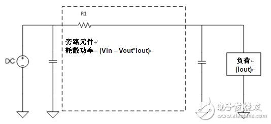
Figure 2. A linear regulator in a simplified mode at steady state can show the location of power dissipation.
This is the way I used to find a linear regulator in the first stage, to determine the package and, more importantly, to determine the power in the package. To calculate power consumption, you can go very quickly to the problem of choosing the package size.
1. Calculate power consumption. A linear regulator is just a variable resistor used to convert an extra voltage drop into heat:
Pd= (Vi-VOUT)*IOUT (Equation 1)
2. Calculate the θjA required to design the desired maximum operating temperature. θjA is the junction thermal impedance relative to ambient temperature, based on a printed circuit board (Celsius / W) package, typically at a typical maximum junction temperature of 150 ° C (the maximum junction temperature of some components may be lower, on the data sheet) Confirmed under the conditions. The required θjA should be the following equation:
≤ (highest junction temperature - maximum operating temperature) / Pd (Equation 2).
1) Filter out the components in the package so that θjA is lower than the above calculations that meet this initial junction temperature requirement. Operating at the highest junction temperature will affect its reliability. Depending on the board, airflow, environment, and other nearby heat sources, leaving a margin is always a good design practice.
2) As long as the list is reduced according to the heat demand, the difficulty of implementing other functions can be greatly reduced, such as: fast transient response, good power state, enabling, low noise, and the like.
3) Test the final result! It is more valuable to use a thermocouple test in the lab for a minute rather than a few hours.
The calorie value can be easily calculated using this thermal calculator.
Thermal analysis can be examined in more depth, and the first analysis helps to filter out parts that are not working properly and find parts that are more likely to work properly.
The main circuit of the equipment is the full bridge controlled circuit and the trigger circuit is the programmable integrated circuit. The phase-shifting, fixed width and modulation of the pulse are all digitized, and it does not need any adjustment for the section of the trigger. It has the features of high reliability, high pulse symmetry, strong anti-interference ability, quick reaction, as well as the advantages of no heat-generating, constant current, energy-saving which is compared with the discharge with the electrical resistance.
Battery Maintenance Charger,Battery Maintenance Equipment,Charging And Discharging Equipment,Battery Charge Discharge Machine
Xinxiang Taihang Jiaxin Electric Tech Co., Ltd , https://www.chargers.be