Approximate requirements: Design an FSK modem with a baseband signal rate of 2000B/s, carrier frequencies of 4kHz and 8kHz, and the ability to fully restore the baseband signal after demodulation. There are multiple implementation approaches, but most modems in the communication field rely on hardware circuits. Given my personal preference for programming (though I still have limited knowledge of circuit design), I decided to implement this using STM32 through pure software. While it may sound complex, it's actually manageable, though there are many details to consider carefully.
The overall design concept is as follows:
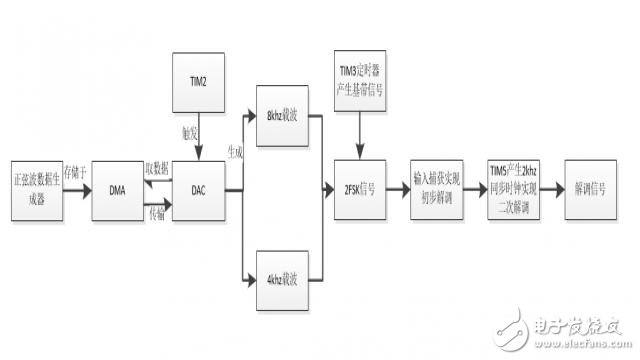
The first step is generating the baseband signal, which is the data we want to modulate and demodulate. The baseband signal consists of a sequence of random symbols. To simulate this, I used a timer to create an 8-bit PN code sequence at a symbol rate of 2000 B/s. Timer 3 is set to trigger every 0.5ms. Each time an interrupt occurs, the variable 'num' increments by one, and the IO pin level is updated accordingly. The 8-bit PN code is repeated eight times, after which 'num' is reset.
TIM3_Init(499,71); // Baseband signal
U8 num = 0;
Void TIM3_IRQHandler(void)
{
If (TIM_GetITStatus(TIM3, TIM_IT_Update) != RESET)
{
Num++;
Switch (num)
{
Case 1: Base_Signal = 1; break;
Case 2: Base_Signal = 0; break;
Case 3: Base_Signal = 0; break;
Case 4: Base_Signal = 0; break;
Case 5: Base_Signal = 1; break;
Case 6: Base_Signal = 0; break;
Case 7: Base_Signal = 1; break;
Case 8: Base_Signal = 0; break; // PN code sequence
}
If(num == 8)
Num = 0;
TIM_ClearITPendingBit(TIM3, TIM_IT_Update);
}
}
Next, the carrier signal is generated. The carrier is a sine wave, with frequencies of 4kHz and 8kHz required. I used the STM32’s DMA + DAC + TIM2 to generate the sine wave. A sine wave generator was used to create 64 sample points with 12-bit precision, stored in the array Sine12bit[]. However, the data sent to the DMA isn't the raw data—it is further processed before being transmitted.
Uint16_t Sine12bit[64] = {
0x7FF, 0x8C8, 0x98E, 0xA51, 0xB0F, 0xBC4, 0xC71, 0xD12, 0xDA7, 0xE2E, 0xEA5, 0xF0D, 0xF63, 0xFA6, 0xFD7, 0xFF5
, 0xFFE, 0xFF5, 0xFD7, 0xFA6, 0xF63, 0xF0D, 0xEA5, 0xE2E, 0xDA7, 0xD12, 0xC71, 0xBC4, 0xB0F, 0xA51, 0x98E, 0x8C8
, 0x7FF, 0x736, 0x670, 0x5AD, 0x4EF, 0x43A, 0x38D, 0x2EC, 0x257, 0x1D0, 0x159, 0x0F1, 0x09B, 0x058, 0x027, 0x009
, 0x000, 0x009, 0x027, 0x058, 0x09B, 0x0F1, 0x159, 0x1D0, 0x257, 0x2EC, 0x38D, 0x43A, 0x4EF, 0x5AD, 0x670, 0x736
};
Uint32_t Idx = 0;
Int main(void)
{
Ei 41 Transformer,Ei41 Line Transformer,B11416 Transformer,Ei Type Transformer,transformer manufacturers
Guang Er Zhong(Zhaoqing)Electronics Co., Ltd , https://www.geztransformer.com