The marquee is also called the lantern and the string of lanterns. Woven into a horse's head from bamboo. The horsetail, which is covered with brightly colored paper, has now been replaced by silk. In the past, the marquees were usually performed on festive days such as the Spring Festival. They were composed of twenty-one 11-year-old children. They sang while jumping, forming different battles according to the pace of the rhythm. There were festive, Ding Cai and Wang Feng. The meaning of the. Now used to refer to an effect achieved by programming on a computer, usually means that a small strip of information is sometimes needed to display a small amount of information that the user is particularly concerned with. This string of information is connected end to end and scrolls in one direction (also often used in practical applications). "Marquee" to monitor whether it crashes.
2, three-color marquee control design preparation 2.1, system operating environment and development toolsThe system running environment is windows7 Ultimate; development tools include: KeiluVision4, ProtuesISIS, Protel99SE.
2.1.1, introduction to program developmentThe K51 program control light is programmed by KeiluVision4 software to achieve the preset effect. Protel99SE is used to draw the schematic diagram, and the simulation of the single-chip effect is performed in Protues.
2.2, device selectionSelecting the minimum system board of 51 single-chip microcomputer, eliminating the tedious time of minimum system design and production; secondly, the single-chip model is STC51; actually need 24 LED lights, divided into three colors: red, yellow, green, buy 30 lights to Can not be replaced after damage; the sound part, two speakers; In addition, you need an ISP download module and two USB power cords for program loading and power input; the remaining 330? There are a number of exclusions, a number of pin headers, and a number of 6*6*6 microswitches.
2.3, schematic design (Figure 1)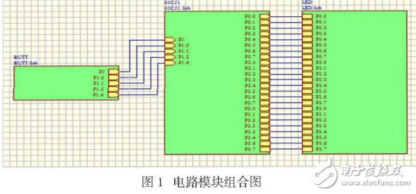
The program written in KeiluVision4 is loaded into the single-chip microcomputer in ProtuesISIS, and then simulated, and the corresponding control operations are respectively performed to see whether the output of each program is implemented as expected.
The debugging of the program is also divided into modules, and one function is regarded as one module. When debugging the module, other functions are masked out. The main function uses a while(1) statement to implement the control loop, so that the program continuously judges and executes the corresponding functions. As long as the conditions for controlling the execution of the program are always satisfied, the different modules can be simulated and debugged. If the corresponding function simulation is different from the expected effect, analyze the relevant information, determine the cause of the error, list the possibility of the error, and then modify the corresponding program code in the corresponding program, and check each one until the corresponding The schematic diagram of the schematic 2 is used to debug the next function.
After all the modules have been debugged, comprehensive debugging is performed. Comprehensive debugging means that each function must be executed. First, each function is executed once, and then switching between different functions. It should be noted that switching may occur during the switching process or the state after switching cannot be related to the corresponding function. Corresponding, or there is a sudden change when switching, the corresponding display is not normal, these are due to the excessive degree of the level code in the function switching is not controlled, the reason may be that the judgment condition is not correct or does not take into account the condition after the state switch .
Through simulation debugging, most of the problems in the program can be found, but some problems not only need to be simulated and debugged, but also analyze the code, consider the program one by one, and go through the program several times. The corresponding calculations can be used to achieve the desired results to the greatest extent.
The patch antenna, also known as a microstrip antenna, is a type of planar antenna that has found widespread application in modern communication systems due to its low profile, lightweight, and ease of integration with various electronic devices. This article delves into the various classifications of patch antennas, highlighting their unique features and areas of application.
1. Shape Classification
Patch antennas can be categorized based on their shape, which significantly influences their radiation patterns and performance characteristics.
-
Rectangular Patch Antennas: The most common form, rectangular patch antennas offer simple design and fabrication processes. They exhibit a directional radiation pattern with a main beam along the broadside of the antenna.
-
Circular Patch Antennas: Circular patch antennas offer a more omnidirectional radiation pattern, making them suitable for applications requiring broad coverage. They are also visually appealing and can blend seamlessly into various environments.
-
Other Shapes: Innovations in antenna design have led to the development of patch antennas with irregular shapes, such as triangular, hexagonal, and elliptical. These unique shapes can offer customized radiation patterns tailored to specific application requirements.
2. Feeding Mechanism Classification
The method of feeding the antenna, i.e., how the RF signal is coupled to the antenna, is another critical aspect of patch antenna classification.
-
Microstrip Line Feed: In this method, the feedline is placed parallel to the patch and connected to it via a gap or coupling aperture. It offers good impedance matching and ease of integration with microstrip circuits.
-
Coplanar Waveguide Feed: This technique involves placing the feedline in the same plane as the ground plane, simplifying fabrication and reducing cross-talk between adjacent antennas.
-
Aperture-Coupled Feed: Aperture-coupled patch antennas use a slot in the ground plane to couple the feedline to the patch. This method provides better isolation between the feed network and the radiating element, resulting in improved antenna performance.
GSM Patch Antenna,FM AM Patch Antenna,2.4G patch Antenna,4G Patch Antenna,5G Patch Antenna
Yetnorson Antenna Co., Ltd. , https://www.yetnorson.com