introduction
In the field of body electronics, a series of studies have been carried out at home and abroad. Shanghai Institute of Technology Chen Jiaqi and others used the industrial computer and related data acquisition card and CAN bus intelligent interface to build a centralized body electronic test bench. Harbin Institute of Technology Jiao Xiaowei and others used Stateflow graphical modeling tools to build a vehicle body application layer software model that conforms to the AUTOSAR standard, and then use the Targetlink code generation tool to automatically generate code based on the model. Yue Guo and others at Warwick University in the United Kingdom compared the advantages and disadvantages of the development method based on SysML and "Simulink+Stateflo-w" in the development of driving information systems. In this paper body network-based electronic control system development method described frame structure and the high-level language, using UML modeling tool for automatic generation of program code further simplify network design and development of the body, improve the degree of software reuse and reduce development costs reduce human error.
1 EA and code generation function Enterprise Architect (EA) is a UML modeling and design platform developed by Sparx Systems of Australia. The EA is small and easy to use, and has complete support for the UML standard. In addition to all 13 graphics supporting the UML 2.0 standard, it also supports other extension diagrams, including analysis graphs, custom graphs, demand graphs, maintenance graphs, and users. Interface diagrams, database schema diagrams, documents, business modeling, and business interaction diagrams.
For ease of expansion, customization, and secondary development, EA provides a rich SDK. The Code Template Framework (CTF) is part of the SDK, and the code generation capabilities of EA are implemented using code generation templates based on this framework. The code generation template specifies the conversion process from the UML element to the given programming language, the modification of which is implemented by the code template editor. Open the EA main menu Settings→Code Generation Template, or use the shortcut Ctrl+Shift+P. Code generation templates are written in plain text, and their grammatical style combines the grammatical features of markup languages ​​and scripting languages. This grammar focuses on three basic structures:
(1) Literal text. In the code generation template, except for the blank lines will be ignored, all the definitions and referenced texts that are not macros or variables will be directly output to the generated code as literal text. Such as:
Class % className%
(2) Macro. Macros can be used to access element values ​​in a UML model and to structure the generated code. All macros have two percent signs containing them. The CTF contains six basic macros: template substitution macros, domain substitution macros, tag value substitution macros, control macros, function macros, and EASL code generation macros. It is these rich macro definitions that make EA's powerful code generation capabilities. Still the above example shows that "%className%" is a domain substitution macro, which will be replaced by the current class name in the generated code. Therefore, if the current class is Foo, the output of the statement is "cl-ass Foo".
(3) Variables. Definitions and provide a convenient reference variables to access the data in the code generation template. Variables in the CTF are defined by weak types, ie the data type of the variable can be ignored and a variable can be assigned values ​​of different data types. The value of a variable can come from various macros, literal text contained in double quotes, and references to other variables. Variable definitions and references use the dollar sign plus a legal identifier, such as $foo=%class Name%. The variable $foo will store the name of the current class. You need to use $foo directly when you need to reference this variable.
2 Software and hardware design In order to facilitate debugging and verify the validity of the generated code, this design builds a body network demonstration experiment platform with CAN bus as the backbone and LIN bus as the lower layer network.
2.1 Hardware Topology According to the function and location of the body appliance, the topology layout of the lab bench is shown in Figure 1. Among them, the thick solid line is the CAN bus and its nodes, and the thin solid line is the UN bus and its nodes. There are 8 nodes on the trunk CAN bus, which are both the host node on the lower LIN network and the CAN/LIN gateway. Among them, the data acquisition node is built using USBCAN card, and the other gateway nodes use Freescale 16-bit single-chip MC9S12XSl28 as the main control chip.
This article refers to the address: http://
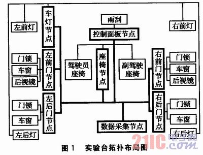
The MC9S12XSl28 has both a CAN network controller (MSCAN module) and a LIN network controller (SCI module), so the hardware design of the CAN/LIN gateway node can be completed by simply connecting the corresponding CAN network transceiver TJAl050 and the LIN network transceiver TJAl020. . The functional block diagram of the CAN/LIN gateway node is shown in Figure 2.

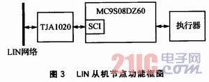
The LIN slave node uses Freescale's 8-bit single-chip MC9S08DZ60 as the main control chip, and uses its SCI module to connect the LIN network transceiver TJAl020, and then connects with other peripheral actuators. The functional block diagram of the LIN slave node is shown in Figure 3.
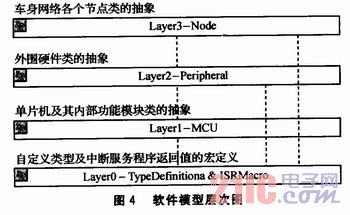
2.2 Software Modeling At present, most software compilers supported by single-chip microcomputers are mainly based on C language, but there is no related concepts such as class and inheritance in C language. At the same time, for the sake of portability, the software model is divided into Layer thought. The software structure of the whole design is divided into four layers: the 0th layer is the macro definition of the type definition and the return value of the interrupt service program, the first layer is the abstraction of the single chip microcomputer and its internal function module class, and the second layer is the abstraction of the peripheral hardware class. The third layer is an abstraction of the various node classes of the body network. The upper class implements specific functions by calling the functions provided by the lower class. The dependencies of each layer are shown in Figure 4. Among them, the dotted line indicates the calling relationship. The modeling methods of the first to third layers will be specifically described below.
2.2.1 The first layer of a single-chip microcomputer and its internal function module class abstraction layer 1 function function through the read and write of the microcontroller register, so use the member function of the class, write the register read and write code directly in the member The Ini-tial box of the function Behavior property. For example, the code of the MSCAN module in S12 is as follows:
CANCTL1(MSCANx)|=CANCTlLl_CANE_MASK;
CANCTL1 is a function macro that is designed to facilitate the uniform processing of multiple MSCAN modules and to manually select a specific module. When using, simply assign MSCANx to the corresponding integer value (for MC9S12XSl28, it can be O~4).
2.2.2 Layer 2 - Abstraction of the peripheral hardware class Layer 2 needs to call the operation of the layer 1 class, which can be implemented by the activity diagram. In the activity diagram, create a new Action, select CallOperation or Call Behavior as needed, and then specify which member function or behavior to call (the called parameters are passed through the Arguments property of the Action). ). Finally, connect the various actions according to the program flow.
Here, a data frame is sent using the CAN protocol (upper layer protocol uses J1939) (activity diagram slightly - editor's note). In order to be able to implement code generation for behavioral diagrams (including activity diagrams), all behavior diagrams and their elements must be placed in a class. The code generated after the activity diagram has been converted is as follows: 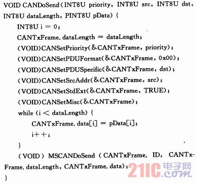
2.2.3 The abstraction of each node class of the third layer and the body network In addition to the operations of the first layer and the second layer, the layer 3 also needs to model the interrupt service program (ISR). Modeling of ISR involves two issues: the return value of the ISR and the location of the ISR.
(1) The return value of ISR. CodeWarrior supports two ways of declaring ISRs. One is to use the precompiled directive pragma to define a TRAP_PROC symbol. TRAP_PROC will prompt the compiler that the function below is an ISR. The compiler will end this function (usually the RTI instruction) with a special interrupt return instruction. This method needs to modify the PRM file in the CodeWarrior project at the same time, and associates the ISR with the vector in the interrupt vector table, which is inconvenient to use UML modeling.
The other is to use the interrupt keyword similar to C51 and specify the corresponding interrupt vector number, thus completing the ISR declaration and association with the interrupt vector table. Modify the code generation template of the class in EA, add a stereotype and name it define, and add the corresponding template code. The core part of the code is as follows: 
After the modification is completed, in the modeling process, you only need to set the class's derivation to define, set the class name to the newly defined symbol, and set the class's parent class to the original symbol. Taking the return value of the CANO module's receive interrupt as an example, the class name can be set to ISR_CAN0_RX, and the parent class can be set to interrupt 38void (this parent class does not exist). The resulting code is as follows:
#define ISR_CAN0_RX interrupt 38 void
Then specify the return value of the ISR as ISR_CANO_RX.
(2) The problem of positioning of ISR. The declaration and definition of the interrupt service routine must be located in the non-banked area, using "#pragma CODE_SEG NON_BANKED". At the same time, "#pragma CODE_SEG DEFAULT" needs to be added at the end of the interrupt service routine, otherwise the latter function will also be located in the non-banked area and cause an error. Therefore, the interrupt service routine must be surrounded by "#pragma CODE_SEG NON_BANKED" and "#pragma CODE_SEG DEFAULT". This can also be done by modifying the code generation template. In combination with the macro definition of the ISR return value, it is only necessary to output the above two pragma precompilation instructions before and after the function when the first three characters of the function return value are "ISR". The core part of the code generation template that generates the ISR declaration is as follows: 
Still taking the reception interrupt of the above CAN0 module as an example, the finally generated function is declared as follows; 
3 Debugging and verification In addition to using the USBCAN card as the data acquisition node, this design verifies that the implementation of the two bus protocols conforms to the standard, more intuitively checks the values ​​of the fields in the bus frame, and detects whether a frame error occurs on the bus at any time. Use the PC oscilloscope PicoScope 5203 with the bus protocol analysis software WaveBPS to capture two bus signals and perform protocol analysis. Pi-coScope's two channels capture signals on both the CAN bus and the LIN bus, further facilitating the debugging of gateway nodes.
Figure 5 is a CAN data frame sent to the light node (target address 0x20) when the left turn signal is turned on at the control panel node (source address 0x26). Wherein, the bit labeled S is a padding bit that is automatically inserted according to the bit stuffing rule. 6 is a data frame sent by the vehicle lamp node to the LIN bus according to the gateway routing policy and the frame conversion rule after receiving the CAN data frame.

4 Conclusion This design uses the code generation function of EA to modify the code generation template to meet the requirements of C language and compiler in the development of body network electronic control system, and develops and preliminary experimental verification of the body network system. This method greatly facilitates design development and improves system reliability.
Accessories for cameras are mainly for care, protection, special effects and functions.
Lens hood: used on the end of a lens to block the sun or other light source to prevent glare and lens flare (see also matte box).
Lens cap: covers and protects the lens during storage.
Lens adapter: sometimes called a step-ring, adapts the lens to other size filters.
Lens filters: allow artificial colors or change light density.
Lens extension tubes allow close focus in macro photography.
Flash equipment: including light diffuser, mount and stand, reflector, soft box, trigger and cord.
Care and protection: including camera case and cover, maintenance tools, and screen protector.
Large format cameras use special equipment which includes magnifier loupe, view finder, angle finder, focusing rail /truck.
Battery and sometimes a charger.
Some professional SLR could be provided with interchangeable finders for eye-level or waist-level focusing, focusing screens, eye-cup, data backs, motor-drives for film transportation or external battery packs.
Tripod, microscope adapter, cable release, electric wire release.
Dew shield - Prevents moisture build up on the lens.
Camera Accessories,Selfie Stick Adaptor,Smartphone Selfie Stick,Threw Hold Camera Accessories
GUANGZHOU WEWOW ELECTRONIC CO., LTD. , http://www.stabilizers.pl