With the rapid development of circuit integration technology, RF circuits tend to be integrated and modular, which is particularly advantageous for the development and application of miniaturized mobile terminals. At present, the RF circuit of the mobile phone is composed of a peripheral auxiliary and control circuit centered on the RFIC. The analysis of the typical functional modules in the RF circuit is the main content of our discussion.
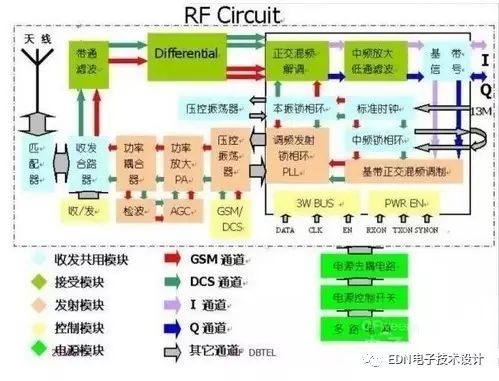
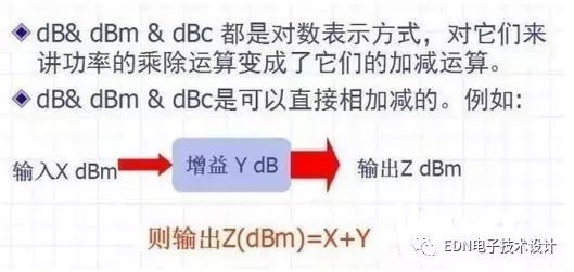
Outline Transceiver Phase-Locked Loop (PLL) Power Control Loop (APC) Transceiver Duplexer Attenuation Matching Network (Matching) Filtering Network (Filter) Balance Network (Balance) Others
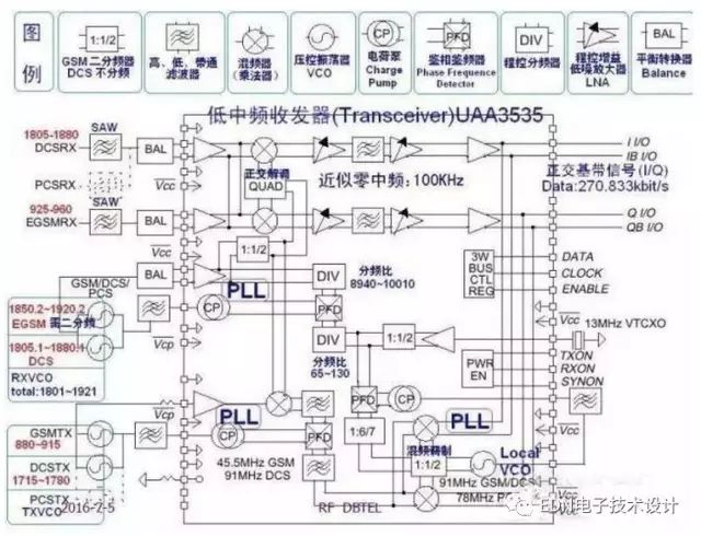
1. Transceiver transceiver is the modem modulation: the baseband signal is transmitted to the radio frequency signal during transmission demodulation: the radio frequency signal is filtered out when receiving the baseband signal Transceiver can be divided into: single frequency, dual frequency, tri-frequency, etc. according to its working frequency. Transceiver can be divided into intermediate frequency, zero intermediate frequency, near zero intermediate frequency, etc. According to the frequency characteristics, the internal structure of Transceiver UAA3535 is introduced. The UAA3535 is a near-zero intermediate frequency transceiver. It can be used for three-frequency transceiver. It has three internal PLLs. (including a built-in VCO), quadrature mixing demodulator, controllable gain low noise amplifier, mixing modulator, etc. It needs to be external: 13MHz reference reference clock, RXVCO, TXVCO, baseband control signal, etc. We need to study its internal Details of the frequency, bandwidth, and signal conversion process of important nodes
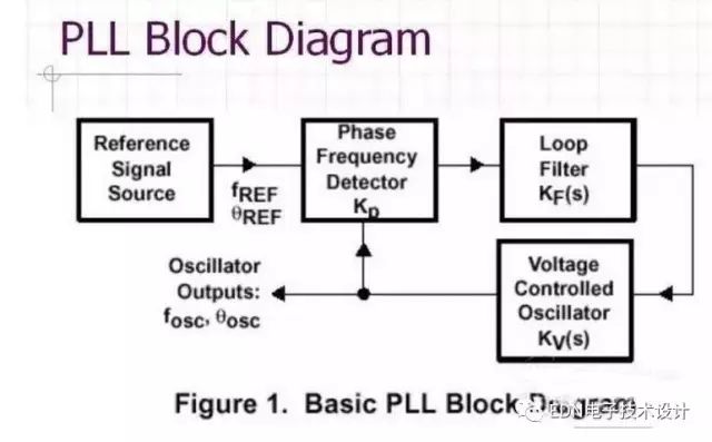
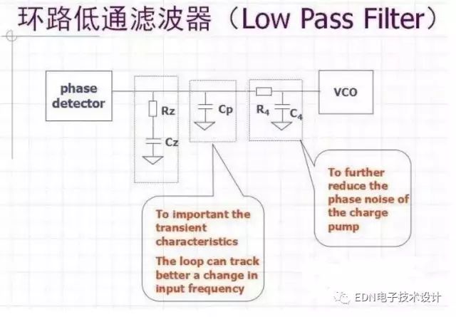
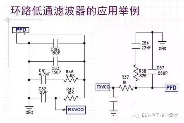
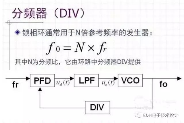
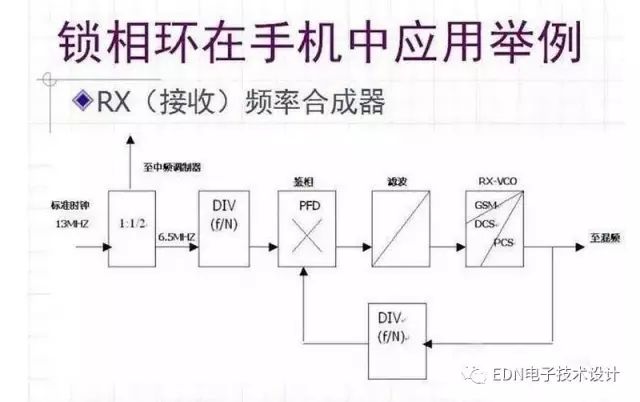
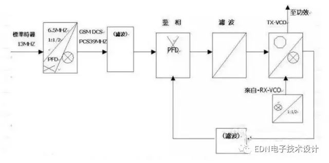
2. Phase-locked loop (PLL) phase-locked loop four basic components: phase detector (PD) discriminator (FD) phase discrimination (PFD): PD / FD / PFD is a phase / frequency comparison device, Used to detect the phase/frequency difference between the input signal and the feedback signal. Loop Filter (LP): LP is generally an N-order low-pass filter voltage controlled oscillator (VCO): VCO is a voltage-frequency conversion The output oscillator frequency should be linearly changed with the input control voltage. Reference signal source: the reference signal source provides a contrast input signal for phase discrimination with the feedback signal.
The basic performance of a phase-locked loop for phase-locked loops includes the acquisition process and synchronization. (1) The performance of the capture process refers to the capture band and capture time. The maximum natural frequency difference allowed by the capture band finger to enter the synchronization state through the capture process is the time interval between the start of the ring route and the time of entering the synchronization state. Frequency deviation capability 》 capture the range. 2) After the loop is locked, the steady-state frequency difference is equal to zero and enters the synchronous state. The steady-state phase difference is usually always present and it is a fixed value. The tracking performance of the loop changes the faster the input signal changes, the worse the tracking performance. The magnitude of transient phase error and steady-state phase error is an important indicator to measure the performance of loop linear tracking. Loop noise performance noise includes input noise and harmonic interference as well as internal noise and harmonic interference. The noise inside the voltage controlled oscillator is the main noise source. The loop capture performance capture band is as wide as possible. The shorter the capture time, the better, which can increase the gain of the loop K or increase the bandwidth of the filter. However, increasing the loop gain or filter bandwidth is often related to improving the loop tracking. Performance and filtering performance requirements are contradictory. Auxiliary capture is used to achieve the goal. Including auxiliary frequency discrimination and frequency discrimination, variable bandwidth and variable gain.
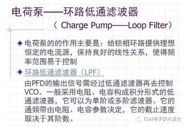
Basic Structure Circuit Analysis Detector Charge Pump - Loop Pump - Loop Filter Voltage Controlled Oscillator Divider (DIV)

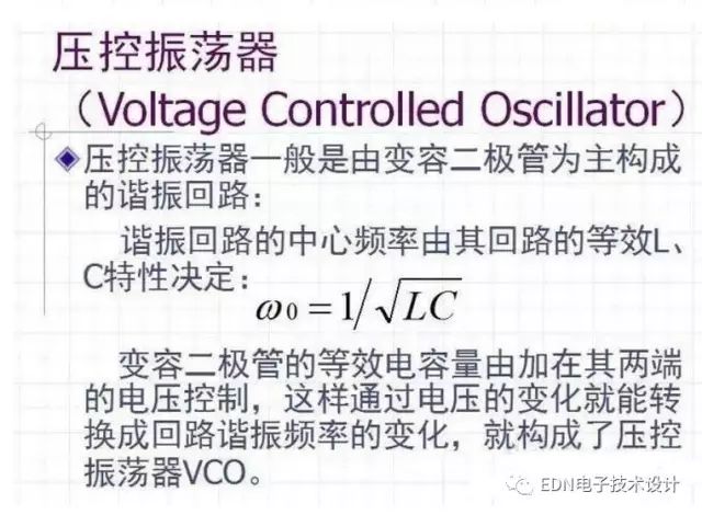
Selection factors of VCO: ◠High spectral purity ◠Linear voltage-frequency transfer characteristic ◠Good frequency stability to temperature ◠Frequency deviation capability 》 The max. PLL capture range ◠Time response ◠Low power consumption and Output level ◠Output harmonic level and tuning Sensitivity◠Phase noise
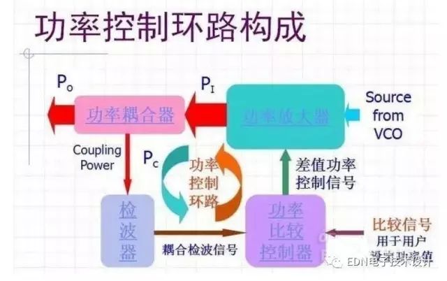
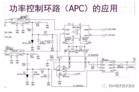
3. Power Control Loop (APC) power control loop consists of Power Amplifier, Power Coupler, Power Detector, Power Comparison, and Controller (Power Comparator & Controller). The loop thus constructed can control the power more stably at our set value, which can be constantly changed as needed.
Power Amplifier Currently, PAs for mobile phones are generally made of thick film analog circuits, which require linear and distortion-free amplification of low-power RF signals to a certain power value. Its main parameters are: â— operating frequency, bandwidth; â— maximum linear output power (compression point); â— linear amplification on input power requirements; â— input and output required matching impedance; â— working power and voltage, current requirements; The form and requirements of the control signal; â— noise characteristics and so on.
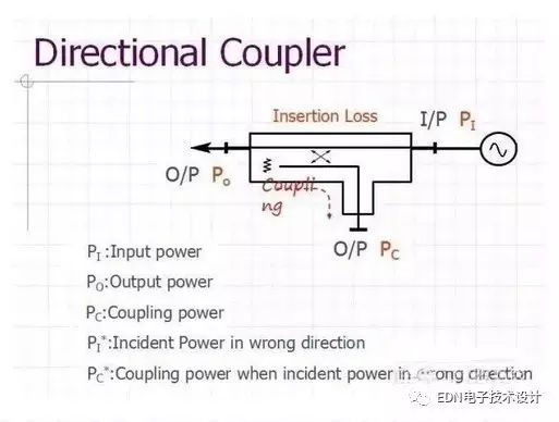
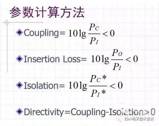
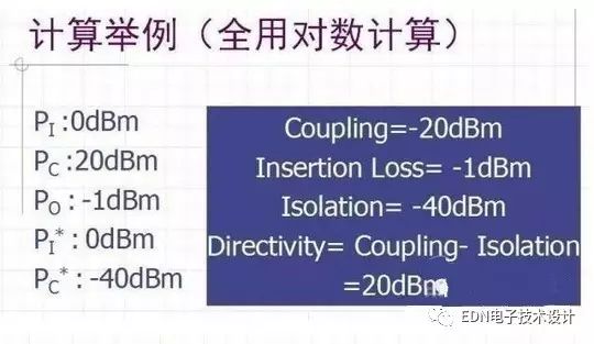
Power Coupler In order to achieve power control, the power sensor we need to use is a power coupler, which is generally a Directional Coupler. Its main parameters are: see its LDC Data Sheet â— Coupling â— Insertion Loss â— Isolation â— Directivity [Unit (dB)]
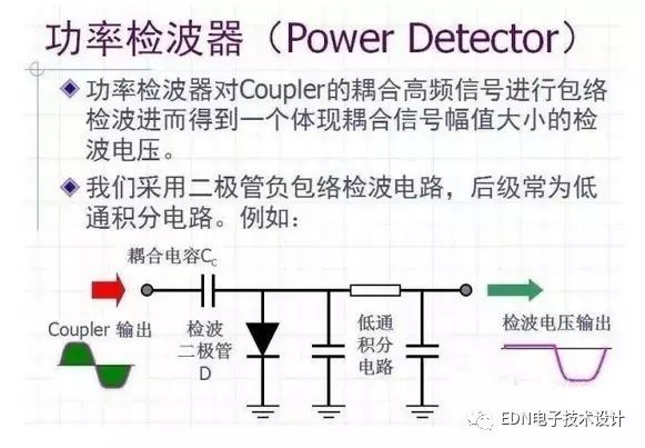
Negative Envelope Detection for Diode Requirements: The detection diode D requires a small Schottky diode with a very small capacitance of the P-input detection diode. If the Pole capacitance is too large, the coupling of the negative envelope will be lost to a low level. , causing the detection effect to deteriorate.
Cigfun is new vape brand released in 2022, designed by experienced vape team from US and UK. Cigfun vapes includ: 600 puffs, 1000 puffs, 2000 puffs, 5500 puffs. E liquid 2ml, 4ml, 8ml, 13ml. Atomizer: cotton coil, mesh coil, ceramic coil. Nic salt strength: 0mg, 20mg, 35mg, 40mg, 50mg. Vape battery: 400mah, 550mah, 650mah, 850mah, 1200mah.
Cigfun is manufactured by China factory with 8 years' experience, supplying high quality Disposable Vapes to USA, UK, Mexico, Brazil, Russia, France, Finland, Greece... Target at fashion, young, cool and well understanding of customer's culture and habits, Cigfun has a model just made for you.
Cigfun vapes are closed system, non-refillable, disposal after you smoke out
Vape Cigfun,Cigfun Vape,Vape Pen Cigfun,Cigfun Disposable Vape,Vape Cigfun Didposable
Shenzhen Axiswell Technology Co., Ltd , https://www.medhealthycare.com