1 Introduction
With the gradual ban on the import and sale of ordinary lighting incandescent lamps, new, green, efficient and long-life LED lighting technologies have achieved unprecedented development [1]. Long life is LED  One of the biggest advantages of lighting, its average service life reaches 80,000-100,000 hours [2]. For single-stage LEDs  Drive power supply, if using mains supply, in order to achieve high power factor (PF), meet the harmonic requirements of IEC61000-3-2 [3], LED lighting requires a power factor correction converter (Power Factor Correction, PFC ). When the power factor is 1, the input current is a sine wave with the same phase as the input voltage, so its input power exhibits a pulsating form with twice the input frequency. For a constant output power LED, in order to match the instantaneous input and output power imbalance, it is required. A storage capacitor. The storage capacitors are very large, most of them use electrolytic capacitors, and the life of electrolytic capacitors is only about 10,000 hours [4], which is the main component that affects the overall life of LED drive power. In order to improve AC-DC  LED drive power supply life, it is necessary to remove electrolytic capacitors. Properly reduce the power factor to reduce the input power ripple, such as injecting the third and fifth harmonics [5, 6] into the input current, thus reducing the size of the storage capacitor. The pulsating current is used to drive the LED so that the instantaneous input and output power are the same or close, and the storage capacitor can be reduced or eliminated [7-10]. The pulsating current drive LED is generally used for landscape or street lighting, and is not suitable for some occasions where the quality of the light source is high. The use of an inductor as an energy storage component can replace or reduce the storage capacitor, but the energy storage density of the inductor is small, its volume is large, and there is also loss [11]. Increasing the voltage wave on the storage capacitor can reduce the capacitance of the capacitor [12-14]. Literature [13] proposed a frequencyless
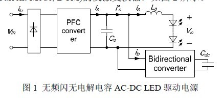
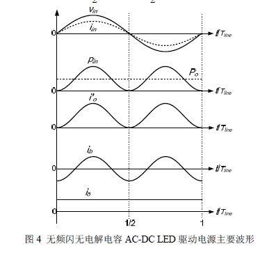
Flashless electroless capacitor AC-DC Â LED drive power, as shown in Figure 1. It consists of a PFC converter, a bidirectional converter and a CL filter. The inductor Lo and the capacitor Co form a low-pass filter to prevent the switching frequency and its multiple times of current harmonics from flowing into the LED. Therefore, the capacitor Co does not bear the energy storage function, and a thin film capacitor or a ceramic chip with a small capacity can be used. Capacitor, at this time the PFC output current i'o contains twice the input frequency of the ripple current. In order to make the driving current io of the LED a constant DC current, a bidirectional converter is connected in parallel with the output of the PFC converter, and the input current ib of the bidirectional converter is equal to the AC component of the input frequency twice in the PFC output current. This solves the stroboscopic problem of LED lighting. The DC-side capacitor Cdc of the bidirectional converter adopts a method of reducing the capacitance of the storage capacitor voltage and large ripple. In the case of the same ripple voltage, in order to further reduce the capacitance,
To properly increase the DC average voltage of Cdc.
This article is in strobo-free electroless capacitor AC-DC Â Based on the LED driving power supply, the nonlinear problem caused by the DC-side capacitor ripple of the bidirectional converter to the duty cycle of the bidirectional converter is analyzed. Because the traditional linear control method cannot provide this part, it is finally reflected in The steady-state error of the bidirectional converter current tracking is increased, and the LED driving current is distorted. Aiming at the problems in the AC-DCLED driverless power supply without stroboscopic electroless capacitor, this paper proposes an improved control strategy in the bidirectional converter to reduce the influence of nonlinear problems caused by DC side capacitor ripple and improve the bidirectional transformation. The ability to track sinusoidal AC references eliminates distortion of LED current.
2. Basic concept of stroboscopic electroless capacitor AC-DC LED driver
The working principle of the stroboscopic electroless capacitor AC-DCLED driving power supply is analyzed in detail in [13]. This paper only introduces briefly. The PFC converter here uses a flyback converter of the Discontinuous Current Mode (DCM), as shown in Figure 2.
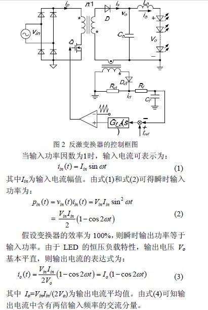
The flyback converter uses average current control to achieve a constant average output. As can be seen from the above analysis, since there is no electrolytic capacitor, the pulsating current contains twice the AC component of the input frequency, which causes the strobe of the LED to emit light. To this end, a bidirectional converter is connected in parallel with the filter capacitor Co of the flyback converter. In this paper, a Buck/Boost bidirectional converter is used, as shown in Figure 3. After adding the bidirectional converter, the DC current mainly flows through the Lo, and the high-frequency current ripple is small. Therefore, it can be considered that the voltage across the capacitor Co, that is, the input side voltage of the bidirectional converter is equal to the voltage Vo across the LED.
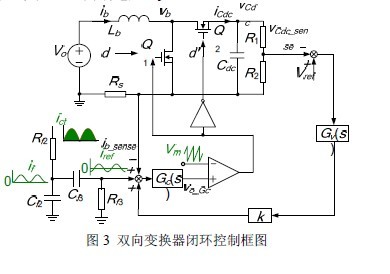
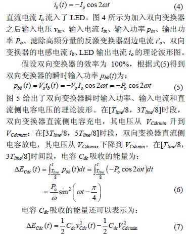
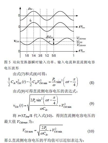
The bidirectional converter uses double closed loop control. In order for the Buck/Boost bidirectional converter to work properly, it is necessary to ensure that the lowest voltage of the DC side capacitor Cdc is higher than the input terminal voltage Vo. The voltage outer loop controls the average value of the DC side capacitor voltage, and its output is added to the given current reference iref (the AC component of the double input frequency is obtained by filtering the secondary side current of the sampling flyback converter) by the proportional coefficient k. As the reference of the current inner loop, the current inner loop adopts the average current control, so that the average value of the input current of the bidirectional converter tracks the current reference, then the current of the output of the flyback converter is shunted, and the AC component of the double input frequency flows into the two-way. The converter is obtained from equation (4):
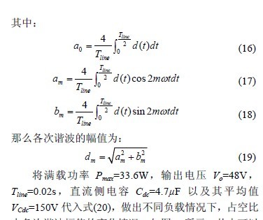
It is found that the DC component of the duty cycle does not change with the load due to the constant value of the DC side capacitor voltage; as the load increases, the ripple of the capacitor increases, and the low frequency component of the required duty cycle increases rapidly. This will make the linear current regulator insufficient to provide this part of the low frequency component, and can only compensate for these low frequency components by increasing the steady state error of the current tracking, eventually leading to the LED  The output current is distorted. If the load Po=Pmax, then the variation of the harmonic amplitude of the duty cycle under different capacitance values ​​under full load condition is made, as shown in Fig. 7. In the case of constant load and DC side capacitor voltage, as the capacitance decreases, the duty cycle low frequency component increases rapidly. Therefore, it is possible to consider designing a nonlinear controller according to the duty cycle expression without affecting system stability. under the premise, the bidirectional converter to achieve sinusoidal current reference no difference trace, reducing the duty ratio of the LED linear  The effect of the output current.
3.2 Implementation of improved control strategy
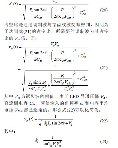
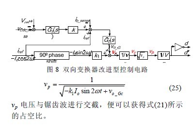
The idea of ​​variable duty cycle control has been applied to high power factor DCM PFC converters [15], which is applied to the control circuit of bidirectional transformers. Observing equation (15), if the duty cycle of the bidirectional converter switch Q1 changes according to the theoretical value during the power frequency cycle, the DC side capacitor voltage of the bidirectional converter will change according to the theoretical form, then the input current will also AC reference change of twice the input frequency. Since the bidirectional converter switches Q1 and Q2 are complementary conducting, for the sake of simplicity, the control switch Q2 is selected here, and the duty ratio d' can be obtained by the equation (15):
4. Simulation verification
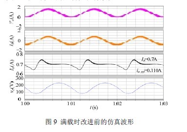
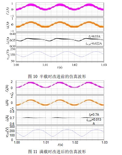
In order to verify the improved control strategy, the steady-state error of bidirectional converter current tracking can be reduced, and the distortion of LED drive current can be reduced. A stroboscopic electroless capacitor AC-DC with improved control strategy is built with Saber software.  LED drive power. The main parameters are as follows: AC input voltage is 220 VAC/50Hz, full load output average current Io=0.7A, output voltage Vo=48V, bidirectional converter inductance is 1.4mH, DC side capacitance is 4.7μF, and the average value of the voltage is 150V, sawtooth amplitude Vm = 3V. Figure 9 and Figure 10 show the simulated waveforms of the secondary current of the high frequency component, the inductor current of the bidirectional converter, the LED output current and the storage capacitor voltage, respectively, under full load and half load conditions. It can be found that the peak-to-peak value of the full-load output current is 110 mA, which is 15.7% of the average value of 700 mA; the peak-to-peak value of the output current at half load is 22 mA, which is 6.3% of the average value of 350 mA, and the LED output current is highly distorted.
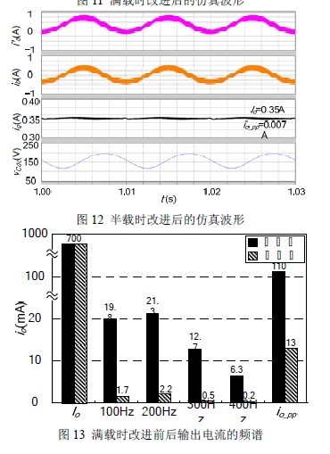
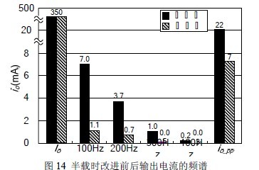
Figure 11 and Figure 12 show the simulated waveforms at full load and half load with improved control strategy. The peak-to-peak value of the output current is 13 mA at full load, which is 1.9% of the average value. The output current is under half load. The peak-to-peak value is 7 mA, which is 2.0% of the average value. Figure 13 and Figure 14 show the spectrum of the full-load and half-load output currents before and after improvement. It can be found that the improved control strategy can greatly reduce the low-frequency components in the LED drive current and suppress the distortion of the LED output current. The correctness and effectiveness of this method.
5 Conclusion
This article is for stroboscopic electroless capacitor AC-DC Â The Buck/Boost type bidirectional converter in the LED driving power supply performs a steady-state analysis, and analyzes the nonlinearity problem of the bidirectional converter caused by the DC side capacitor voltage ripple, in order to reduce the bidirectional converter input current to twice the power frequency alternating current. Based on the tracking error of the reference, an improved nonlinear control strategy with variable duty cycle is proposed to improve the original LED drive current distortion.
Rf Phase Shifter,Digital Phase Shifter,Wideband Phase Shifter,Waveguide Phase Shifter
Chengdu Zysen Technology Co., Ltd. , https://www.zysenmw.com