One of the basic tasks of machine vision is to acquire image information from a camera and calculate geometric information of objects in three-dimensional space to thereby reconstruct and identify objects. The relationship between the three-dimensional geometric position of a point on the surface of a space object and its corresponding point in the image is determined by the geometric model of the camera imaging. These geometric model parameters are camera parameters. Under most conditions, these parameters must be obtained through experiments and calculations. This process is called camera calibration (or calibration). The calibration process is to determine the geometric and optical parameters of the camera and the orientation of the camera relative to the world coordinate system. Due to the accuracy of the calibration, it directly affects the accuracy of computer vision (machine vision). Therefore, only after the camera calibration work is done, the follow-up work can be started normally. It can be said that improving the calibration accuracy is also an important aspect of current scientific research work.
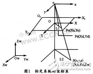
The camera projects a three-dimensional scene onto the camera's two-dimensional image plane through an imaging lens, which can be described by an imaging transformation (ie, a camera imaging model). The camera imaging model is divided into a linear model and a nonlinear model. The pinhole imaging model belongs to the linear camera model. This paper discusses the transformation relationship between a spatial point and its image projection point in various coordinate systems under this model. Figure 1 shows the relationship of three different levels of coordinate systems under the pinhole imaging model. Where (Xw, Yw, Zw) is the world coordinate system, (x, y, z) is the camera coordinate system, XfQfYf is the image coordinate system in pixels, and XOY is the image coordinate system in millimeters.
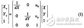
The relationship between the coordinates of a point in the image coordinate system in the image and the coordinates in the image coordinate system in pixels is as follows:
The relationship between the coordinates of a point in the world coordinate system and the coordinates in the camera coordinate system is as follows:
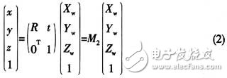
Where is 3 & TImes; 3 orthogonal unit moments; t is a three-dimensional translation vector; M2 is 4 & TImes; 4 matrix.
Because the pinhole imaging model has the following relationship:
Therefore, the homogeneous coordinates and matrix representations of (1), (2) substituted into the above formula are available:
Among them, M1 is the camera internal parameter, and M2 is the camera external parameter. Determining a camera parameter is called camera calibration.
2 Calibration classificationIn general, camera calibration can be divided into two categories: traditional camera calibration methods and camera self-calibration methods. The basic method of traditional camera calibration is to obtain the internal parameters and external parameters of the camera model by performing image processing on a specific calibration reference object and calculating and optimizing it using a series of mathematical transformation formulas under a certain camera model. However, this method is difficult to achieve in the general case where the scene is unknown and the camera is arbitrarily moving. In the early 1990s, Faugeras, Luong, Maybank et al. first proposed a camera self-calibration method. This self-calibration method is calibrated by the constraint relationship between the parameters of the camera itself, and is not related to the motion of the scene and the camera, so it is more flexible.
2.1 Camera calibration based on 3D stereo target Camera calibration based on 3D stereo target is to place a 3D stereo target in front of the camera. The vertices of each small square on the target can be used as feature points. The position of each feature point relative to the world coordinate system should be accurately determined at the time of production. After the camera obtains the image of the feature point on the target, the equation representing the relationship between the three-dimensional space coordinate system and the two-dimensional image coordinate system is a nonlinear equation of the camera's internal parameters and external parameters. If the nonlinear distortion of the camera lens is ignored and the perspective transformation matrix is ​​omitted Given an element as an unknown, given a set of 3D control points and corresponding image points, the direct linear transformation method can be used to solve the individual elements in the perspective transformation matrix. Therefore, the internal and external parameters of the camera can be calculated from the world coordinates and image coordinates of the feature points on the target.
2.2 Camera calibration based on 2D planar targets This method is also known as Zhang Zhengyou calibration method, which is a new flexible method suitable for application. The method requires the camera to shoot a planar target in more than two different orientations. Both the camera and the 2D planar target can move freely, and the internal parameters are always constant. Assuming that the 2D planar target is Z=0 in the world coordinate system, then pass The linear model analysis can calculate the optimal solution of the camera parameters, and then use the basic maximum likelihood method for nonlinear refinement. In this process, after taking the objective function considering the lens distortion, the required internal and external parameters of the camera can be obtained. This calibration method has good robustness and does not require expensive refinement calibration blocks, which is very practical. However, when the Zhang Zhengyou method is used to estimate the linear internal and external parameters, it is assumed that the straight line on the template image is still straight after the perspective projection, and then the image processing is performed. Therefore, the error is actually introduced. Therefore, the 嘎 method has a large distortion in the wide-angle lens. The situation is quite inaccurate.
2.3 Camera calibration based on radial constraints
Tsai (1986) gives a two-step calibration method based on radial constraints. The core of the method is to solve the overdetermined linear equation by least squares method using RAC (radial uniform constraint) condition. Other off-camera parameters (in the direction of the camera's optical axis), and then other parameters of the camera are solved in both the camera and the lensless distortion. The Tsai method is highly accurate and suitable for precision measurement, but it also requires high equipment and is not suitable for simple calibration. The accuracy of this method comes at the cost of the accuracy and complexity of the device.
A method of calibrating a camera using only a correspondence between a surrounding environment image and an image during motion during motion is not referred to as a camera self-calibration method. At present, the existing self-calibration techniques can be roughly divided into camera self-calibration technology based on active vision, camera self-calibration method for directly solving Kruppa equation, layered stepwise calibration method, and self-calibration method based on quadric surface.
3.1 Active vision-based self-calibration The so-called active vision system means that the camera is fixed on a platform that can be precisely controlled, and the parameters of the platform can be accurately read from the computer. It is only necessary to control the camera for special motion to obtain multiple images. The image is then used to determine the camera's internal and external parameters using the image and known camera motion parameters. The representative method is the linear method based on two sets of three orthogonal motions proposed by Ma Weide. Later, Yang Changjiang, Li Hua and others proposed an improved scheme, which is based on 4 sets of plane orthogonal and 5 sets of plane orthogonal motion respectively. The pole information in the image is used to linearly calibrate the camera parameters. This self-calibration method is simple in algorithm and can obtain a linear solution. The disadvantage is that there must be a camera motion platform that can be precisely controlled.
3.2 Self-calibration method based on Kruppa equation
The self-calibration method proposed by Faugeras, Luong, Maybank, etc. is directly based on a method for solving the Kruppa equation, which derives the Kruppa equation using the concepts of absolute quadratic curve and epipolar transformation. The self-calibration method based on the Kxuppa equation does not require projective reconstruction of the image sequence, but establishes an equation between the two images. This method is more difficult than hierarchical layered calibration in some cases where it is difficult to unify all images into a uniform projective frame. It is more advantageous, but at the cost of not ensuring the consistency of the infinity plane in the determined projective space of all images. When the image sequence is long, the self-calibration method based on the Kruppa equation may be unstable. And its robustness depends on the given initial value.
3.3 Stratified step-by-step calibration method In recent years, stratified step-by-step calibration method has become a hot topic in self-calibration research, and gradually replaced the method of directly solving Kruppa equation in practical application. The layered step-by-step calibration method first requires projective reconstruction of the image sequence, and then imposes constraints on the absolute quadratic curve (surface), and finally determines the affine parameters (ie, the infinite plane equation) and the parameters in the camera. The feature of the layered step-by-step calibration method is that on the basis of projective calibration, the projection alignment is based on a certain image, thereby reducing the number of unknowns, and then solving all the unknowns simultaneously through the nonlinear optimization algorithm. The downside is that the initial value of the nonlinear optimization algorithm can only be obtained by estimation, but it cannot guarantee its convergence. Since the projection reconstruction is based on a certain reference image, the reference images are different in selection and the calibration results are different.
3.4 Self-calibration method based on quadric surface
Triggs was the first to introduce the concept of absolute quadrics into self-calibration. This self-calibration method is essentially the same as the method based on Kruppa equation. They all use the absolute quadratic curve under the Euclidean transformation. Not denatured. However, in the case of inputting multiple images and achieving consistent projective reconstruction, the self-calibration method based on quadric surfaces is better, and the root cause is that the quadric surface contains all the information of the infinite plane and the absolute quadratic curve, and The self-calibration method based on quadric surface calculates the quadric surface on the basis of projective reconstruction of all images. Therefore, this method ensures the consistency of all images in infinity plane.
Traditional camera calibration requires calibration of the reference. In order to improve the calculation accuracy, it is also necessary to determine the nonlinear distortion correction parameters. Camera self-calibration has better flexibility and practicability than traditional methods. After more than ten years of unremitting efforts, the theoretical problems have been basically solved. The current research focuses on how to improve the robustness of the calibration algorithm and how well it is. These theories are used to solve practical visual problems. In order to improve robustness, it is recommended to use more hierarchical self-calibration methods and to linearly optimize the self-calibrated results.
Water-cooled capacitor is supercapacitor is a capacitor with a capacity of thousands of farads.According to the principle of capacitor, capacitance depends on the distance between the electrode and electrode surface area, in order to get such a large capacitance, as far as possible to narrow the distance between the super capacitor electrode, electrode surface area increased, therefore, through the theory of electric double layer and porous activated carbon electrode.
Water-Cooled Capacitor,Water-Cooled Power Capacitor,Water-Cooled Electric Heat Capacitor,Water-Cooled Electric Heating Capacitor
YANGZHOU POSITIONING TECH CO., LTD. , https://www.yzpst.com