The system selects the 51 series AT89C51 chip, which is a low voltage, high performance CMOS 8-bit microprocessor with 4kbyte Flash Programmable and Erasable Read Only Memory. Device, commonly known as microcontroller. The device is fabricated using ATMEL high-density non-volatile memory fabrication technology and is compatible with the industry-standard MCS-51 instruction set and output pins. Combining a versatile 8-bit CPU and FLASH Memory in a single chip, ATMEL's AT89C51 is a highly efficient microcontroller that provides a flexible and cost-effective solution for many embedded control systems. The AT89C51 is a low-power, high-performance microcontroller with 40 pins and 32 external bidirectional input/output (I/O) ports. It also contains 2 external interrupt ports, 2 16-bit programmable timing counters, and 2 full The duplex serial communication port, AT89C51 can be programmed according to the conventional method, or can be programmed online.
Infrared transmitting circuit module: How the signal sent by the single chip microcomputer is recognized by the infrared transmitting tube, and whether the transmitting tube can normally emit the infrared signal is a key problem to be solved by the transmitting circuit. To emit an infrared signal, an infrared emitting device must be available. Infrared light-emitting diode (LED) is a kind of light-emitting diode that can generate infrared light. At present, the widely used infrared light-emitting diode emits infrared light with a wavelength of about 940 nm. The shape is the same as that of an ordinary light-emitting diode, but the color is different. Common infrared emitting diodes have black and transparent colors. The biggest difference between them and ordinary light-emitting diodes is that the emitted light is invisible light, while ordinary light-emitting diodes emit visible light of various colors. Generally, infrared light-emitting diodes are divided into two types. Structure: One is a remote-controlled emission type infrared light-emitting diode (ie, the infrared-emitting diode used in the most commonly used hand-held remote controller); the other is a close-range emission type infrared light-emitting diode, which combines the emission and reception of infrared light. As one. Since this design implements a home remote control, the first one can be used. 
As shown in the figure, the system remote control transmission schematic diagram, P1.0 port is the key input port; P2.0 port is the infrared transmission port for outputting 38kHz carrier code, the pulse is amplified by 9013 (NPN) and then output by the infrared transmitting tube; The 9th pin is the reset pin of the MCU, and the RC manual reset circuit is used; the 18 and 19 pins are connected to the crystal oscillator.
Infrared receiving circuit module: The realization of the receiving circuit and the dimming circuit are realized by relays. Each resistor is connected in series with a resistor to form a loop. This circuit connects four relay circuits in parallel and is connected to P0 port. When four relays When both are closed, the light is the brightest. When the three relays work, the light is brighter. When the two relays work, the light is light. When one relay works, the light is the darkest. When the four relays are not working, the light bulb is at Disabled. The receiving circuit diagram is shown in Figure 6: 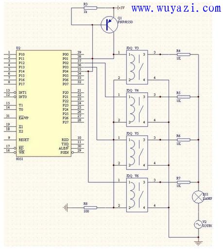
Review analysis:
The demodulation center frequency of the infrared receiver SM0038 used is 38KHz, so the transmission frequency is also 38kHz. This circuit uses one button, one coding method to realize the control of the circuit, and the receiving end realizes the lamp according to the received different number of codes. Adjustment control for different brightness. Each time the P1.0 port is low, it is determined that the key is pressed and a code is transmitted by the P2.0 port. When the receiving end receives the encoding, it is judged whether the first low level is greater than 2 ms. If yes, it is judged whether it is the correct encoding. If yes, num is increased by 1, and the brightness is dimmed by one gear. The biggest difficulty of this design is how to realize the transmission and reception of infrared signals. In order to reduce the cumbersomeness of the circuit, the software can be used to realize the software codec, which can greatly improve the flexibility of the circuit and reduce the cost. It can be realized by only one key. Switching and brightness adjustment of a luminaire, if a key switch is changed to a matrix keyboard, the switch and brightness control of the whole home luminaire can be realized, and the utility model is very practical.
Mobile Game Accessories,Mobile Finger Sleeve,Mobile Wireless Controller,Gaming Gloves
MICROBITS TECHNOLOGY LIMITED , https://www.hkmicrobits.com