With the development of science and technology and the improvement of people's living standards, robots have begun to enter people's lives. With the advent of this era, various new types of robots have emerged, such as cleaning robots and security robots. One of the most important parts of mobile robots: the navigation system, which has attracted more attention in the field of robotics. Robot navigation systems are essential for many robot applications such as smart warehouses, supermarket shopping guides, home robots, automated libraries, and smart hospitals. More common is the line-hunting robot. The actual design found that because of the limitation of fixed lines, this system can not achieve a full range of autonomous operation in the true sense. In addition, this method is greatly affected by light and cannot be practically applied in life. The line on the surface will also affect the appearance of the ground. After a thorough literature search and reflection, a new robot navigation system was proposed, which combines technologies such as RFID, geomagnetic induction and DSP. The actual system hardware and software design and stability tests were carried out.
System motherboard and sensing module
Regarding the power supply, the system is powered by a 12V lithium battery and uses a three-terminal positive voltage regulator to regulate the voltage. Internal integrated power protection. The output current can reach 1A. The input withstand voltage can reach 30V. The charging interface is provided, controlled by the switch, and the interface is left on the circuit board to charge the lithium battery. The positioning device uses radio frequency technology. From the basic principle of information transmission, the radio frequency identification technology is based on the transformer coupling model in the low frequency band and the spatial coupling model based on the radar detection target in the high frequency band (the radar transmits the electromagnetic wave signal to the target and returns the target information to the radar receiver after hitting the target). The most basic RFID system consists of three parts: a tag, a reader, and an antenna. According to the working distance, it can be divided into close-coupled card (acting distance less than 1 cm), near-coupled card (acting distance less than 15 cm), loose coupling card (acting distance is about 1 m) and long-distance card (acting distance from 1 m to 10) M, even further). This system uses a near-coupling card. The RF module communicates with the SCIA port of the 2812. The position of the robot is determined by decoding the data stream.
Followed by the infrared obstacle avoidance module. In general, robots can avoid obstacles by using infrared reflection, which is more common in robot games. The GPIO controls the emission of infrared rays, and then if the obstacles are reflected back, the receiving tube will cause a change in resistance after receiving the light, and detecting the change in resistance can determine whether there is an obstacle. However, this method is susceptible to interference from optical noise. Therefore, the distance is relatively close, generally only 2-3cm. In many competitions, after reviewing the data and research, I proposed a circuit that uses the standard high-frequency signal 38KHZ infrared to detect the obstacle. Because of the use of high-frequency signals and high-frequency op amps, there is a certain anti-interference ability, and the maximum distance of detection is increased to 8cm. First, infrared rays are emitted through 555. Then, after passing through the infrared receiving tube, the signal passes through the DC blocking capacitor and is sent to the high-frequency operational amplifier LM318N. Then, it is amplified by 50 times.
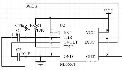
Figure 1 555 transmitting circuit
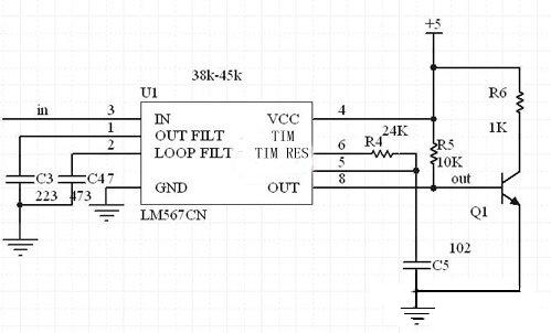
Figure 2 frequency identification circuit
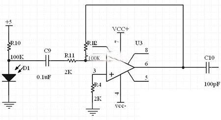
Figure 3 detection amplifier circuit
The LM567 is a phase-locked loop circuit in an 8-pin dual in-line package. The external resistors and capacitors of pins 5 and 6 determine the center frequency of the internal voltage controlled oscillator. The pins 1 and 2 are usually grounded through a capacitor, respectively, to produce an output filter network and a loop single-stage low-pass filter network. The capacitance of the 2-pin connection determines the capture bandwidth of the phase-locked loop: the larger the capacitance, the narrower the loop bandwidth. The center frequency and filter bandwidth of the voltage controlled oscillator can be determined by the equation.
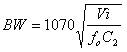 (where Vi is the input voltage)
Then there is the electronic compass module. The CMPS03 electronic compass is a planar angle sensor. By detecting the current sensor's direct angle to the Earth's magnetic field, the electronic compass can achieve an absolute rotation angle of 0.1 degrees. This electronic compass module is specially made for robots in order to provide the robot with the appropriate direction navigation signals. A unique encoding can be generated for any direction. The sensor uses PHILIPS' KMZ51 geomagnetic sensor chip, which has high precision. There are two output modes, the first one: I2C mode, which is output by Pin2 (SCL) and Pin3 (SDA). Pin7 and Pin5 must be left floating. Pin6 is used for calibration. These pins are connected to the motherboard. Since the module is powered by 5V and the DSP is 3.3V, it needs to be level-shifted with 74LVC245. The system is calibrated by Pin6 via the 2812's GPIOB. The calibration only needs to be done once, because the data will be stored in the EEPROM of the PIC microcontroller in the electronic compass. Pin 6 has a pull-up resistor. Calibration is only required to pass a negative phase pulse to Pin6 via GPIO, and because of the pull-up resistor, it is also possible to disconnect this pin from the system.
Finally, the design of the drive module of the system. Use L298 chip. More common is the L298N in a 15-pin Multiwatt package, which also contains a 4-channel logic driver circuit. The power output device included in L298 is designed and fabricated on a quartz substrate. Due to the identity of the manufacturing process, the performance parameters of the discrete component combination circuit are unmatched and the operation is stable. Pin 15 is the output current feedback pin, the other is the same as L293. These two pins can also be directly grounded during normal use. It is a high voltage, high current dual full bridge driver chip. Standard TTL logic levels can be accepted directly. Can drive various loads such as motors, relays, etc. There are two enable inputs through which the effectiveness of the PWM wave is controlled. The L298 integrates two energy output blocks A, B. In addition, we have designed a freewheeling diode on the board.
On the premise of having mature motor design capabilities and high-precision process support capabilities (including automatic CNC metal processing technology, automatic high-speed precision motor stator and rotor punching production process lights), the low Servo Motor built by Kassel can be compatible with ac servo motors. The drive is perfectly matched to maximize the power and performance of the equipment, output unparalleled power density and motion control effects, simple and cost-effective.
Low Inertia Servo Motor,Low Inertia Motor,Low Inertia Servo Motor Control,Low Inertia Servo Motor Robot
Kassel Machinery (zhejiang) Co., Ltd. , https://www.kasselservo.com