Photocoupler
Circuit Operation Principle The time relay circuit consists of a voltage regulator filter circuit, a delay charge and discharge circuit and a relay control circuit, as shown in Figure 8-137.
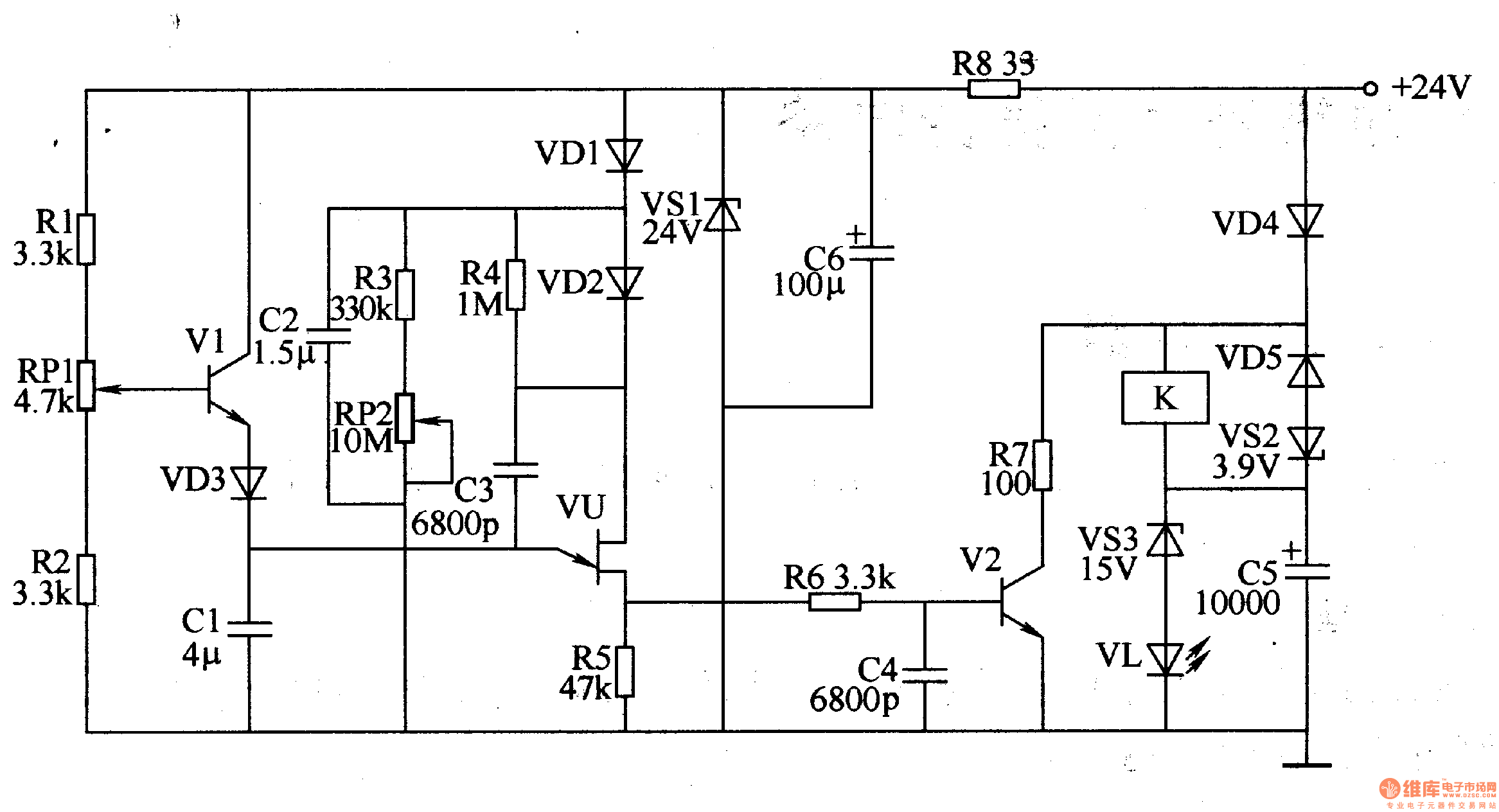
The voltage regulation filter circuit is composed of a resistor R8, a Zener diode VS1 and a filter capacitor C6.
The delay charging and discharging circuit is composed of resistors R1-R5, capacitors RP1 and RP2, transistor V1, capacitor Cl-C3, diodes VD1-VD3, and single-junction transistor VU.
The relay control circuit consists of resistors R6 and R7, capacitors C4 and C5, diodes VD4 and VD5, Zener diodes VS2 and VS3, transistor V2, LED VL and relay K.
Turn on the +24V power supply, K energizes, VL lights up, Vl turns on, Cl charges through VD3 and Vl, C2 charges through VDl, VU and V2 are in the off state. After the circuit is powered off, the VL is extinguished, and the armature of K continues to be in the closed state under the action of the core remanence. Vl is cut off, and C2 is discharged through R3 and R. When the voltage across C2 drops to a certain value, VU is turned on, Cl discharges V2 through VU and R6, turns V2 on, C5 discharges through K coil, R7 and V2, and generates reverse voltage across K coil. , the core of K is demagnetized, K is released, and the delay process ends.
Adjust the resistance of RPl and R to change the delay time (adjustment range is 0.5-205).
Component selection
R1-R6 selects 1/4W metal film resistor for use; R7 selects 2W wirewound resistor for use; R8 selects 1/2W metal film resistor for use.
RP1 selects multi-turn wirewound potentiometer; RP2 selects organic solid potentiometer.
C1 and C2 use monolithic capacitors or CBB capacitors; C3 and high frequency ceramic capacitors or glass glaze capacitors are used; C5 and C6 are aluminum electrolytic capacitors with a withstand voltage of 35V.
VD1-VD5 selects 1N4007 silicon rectifier diode for use.
VS1-VS3 selects 1/2W silicon steady voltage diode for use.
VL selects φ5mm LED.
Vl selects S9013 type silicon NPN transistor for use; V2 selects S8050 type silicon NPN transistor for use.
VU uses BT3l or BT33 type single junction transistors.
K selects the DC relay with residual magnetism after the power is cut off, such as 0A8874.12/266.
Big cloud vape kits for when you want the biggest clouds. All our vape mods ship from China.We are Disposable Vape supplier of big smoke.
Here're the best vape pen with big clouds in 2022.Best Vape disposable in the US.Best Vape Mods in the UK.
Big Smoke,Vape Big Smoke ,Big Smoker Hqd ,Smok Mesh Coil
tsvape , https://www.tsvaping.com