This article refers to the address: http://
This article introduces a self-made sound circuit, using the power amplifier integrated circuit LM1875T developed by National Semiconductor Manufacturing Corporation (NSC) for audio in the 1990s. The main parameters are as follows:
TO-220 single-row 5-pin plastic package, operating voltage range: +8V ~ ± 30V. Undistorted output power: Po>25W, quiescent current: 50mA, maximum current: 4A, input sensitivity: 630mV, open loop gain: 90dB, rated gain: 26dB, distortion: 1kHz20WB, THD=0.015%, conversion rate: 18V /μs, with overload, overcurrent, overtemperature and inductive load reverse potential protection.
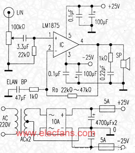
The power amplifier integrated block is small in size, simple in external circuit, large in output power, and small in distortion, not only sound quality is quite good, but also has a rounded taste of the tube machine. It has a relatively complete protection function, the circuit is shown in Figure (one channel, power sharing).
The circuit is very simple. Firstly, use the shielded cable to connect the signal from the computer audio line output jack LINE-OUT to the amplifier. The 2x100kΩ volume potentiometer should use the consistent product as much as possible. The impedance is larger considering the audio output capacity of the computer sound card. The value is smaller, the input impedance is larger, and the low-frequency end response is better. The signal is input to the 1 pin of the amplifier block through the coupling capacitor. The integrated block and the simple peripheral circuit constitute an amplifying circuit. Changing the resistance of the transconductance resistor RD can change the amount of amplification of the unit. The larger the resistance is, the higher the gain is, so as to obtain a suitable local sensitivity and amplification factor, and the resistance is often selected between 22kΩ and 47kΩ. An RC network is added to the output of the power amplifier block to prevent low frequency self-excitation and protect the horn and power amplifier circuit.
Selection of components
The coupling capacitor is a blue metal film CBB non-inductive polypropylene capacitor with a voltage of 3.3μF to 4.7uF and a voltage of 63V. The sound is clear and pleasant, the high frequency is elegant, and the tone is good. After experimentation, the sound quality of any electrolytic capacitor cannot be compared with the CBB capacitor.
The power transformer is selected from the R type or the ring type with a power of >70W, and the EI type with better quality can also be used. The secondary voltage is AC 2×18V to AC 2×22V, and is DC±25V after rectification and filtering. The rectifier bridge current should be above 10A. The main filter capacitor is 2 × 4700μF, and should be selected from Japan ELNA high-speed audio dedicated electrolytic capacitor. The 100μF electrolytic capacitor and 0.1μF CBB capacitor in the circuit diagram are medium and high frequency signal decoupling filter capacitors. The fever should be used to improve the sound performance of the amplifier and high frequency.
Some amplifiers in this amplifier circuit will remove the 47uF feedback capacitor and directly short-circuit when it is in the motor, thus becoming a pure DC amplifier. It is said that the frequency response is better and the low frequency extension is lower. However, the author believes that the mid-point offset voltage drift will have an impact on the line output during high-power playback, or the standard circuit recommended by the manufacturer. In order to improve the sound quality, this feedback capacitor does not use ordinary ordinary products, but uses a dark red Japanese ELNA-BP gold-tone audio dedicated non-polar electrolysis. The sense of hearing is round and mellow, and it does not cause DC zero potential in the integrated block 4 feet. Drift phenomenon.
Circuit installation and debugging
The 3-pin negative power supply terminal of the LM1875 is connected to the heat dissipation end of the chip. Therefore, when the external heat sink is installed, the mica chip must be insulated from the external heat sink, and the external heat sink area must be large enough to facilitate the heat dissipation of the chip. It is better to feel that the hands are not hot. The amplifier can be used with a finished circuit board, and the circuit board can be self-made due to the small number of components.
The debugging of the amplifier is relatively simple. Firstly, ensure that the components of the circuit board are installed correctly. The positive and negative voltages are measured correctly. Do not connect the speakers first. Use the digital meter to measure the 4 pin and ground zero drift of the output of the power amplifier block. If the voltage is within 30mv, it should be considered. Normally, after listening for half an hour without change, you can connect the speaker to the audition. Otherwise, you should first troubleshoot.
As long as the component data is correct, the power supply voltage is positive and negative symmetrical (the voltage value is slightly larger and slightly smaller), and generally can be successfully installed at one time.
Speaker unit and speaker should make the sound quality good. The choice of speaker has a great relationship. You should use the top grade products, such as American elegant, Taiwan Logitech, Japan JVC and other full-range speaker units. Those with conditions can also choose small, high-quality finished speakers with slightly higher sensitivity.
Easy Electronic Technology Co.,Ltd , https://www.nbpcelectronicgroup.com