With the development of electronic technology, many intelligent technologies are widely used in vehicles, and vehicle rearview mirror systems as important safety auxiliary devices have also experienced several generations of technical development [1]. At present, two new technologies have appeared in the vehicle rearview mirror system: rearview camera and reversing radar. The former image is intuitive and true, but it can not give an accurate distance; the latter can accurately measure the distance, but it can not reflect the puddles behind the car, the protruding steel bars, etc., so there is a dead end in safety [2] [ 3]. There are several types of radar ranging on vehicles: laser ranging, microwave ranging and ultrasonic ranging. The first two have a long measuring distance and high measurement accuracy, but the cost is high; the latter has a low cost, but the range is usually small, and the safety is not good when the reversing speed is slightly faster.
This paper proposes a vehicle electronic rearview mirror system based on SOPC technology. The system can display the image behind the vehicle in real time, and uses dual-frequency ultrasound to achieve a large range of more than 10m. At the same time, the system has voice broadcast measurement results and Alarm and other functions. 1 System characteristics
Compared with other electronic reversing systems, this system has the following features: (1) Ultrasonic distance measurement with two frequencies of 40kHz and 25kHz, which not only expands the measurement range but also takes into account the measurement accuracy when measuring in a small range. (2) A 3.5-inch color LCD screen can be used to display the image behind the vehicle in real time and intuitively, while displaying the distance of the obstacle and the speed of the vehicle relative to the obstacle. (3) Voice broadcast distance measurement result and alarm. The voice chip ISD4002 is used to realize the voice broadcast of the distance measurement result, and at the same time, the danger level is automatically evaluated according to the measurement result and the speed of the vehicle relative to the obstacle, and the warning sounds with different urgency levels are used to warn. (4) Adopt SOPC to realize system design, which has good flexibility. 2 Hardware circuit design
2.1 System hardware structure
The circuit block diagram of the vehicle's electronic rearview mirror system is shown in Figure 1. The whole system can be divided into image acquisition and conversion, image and information display, ultrasonic ranging, voice broadcast and warning, temperature measurement and other parts. The CMOS image sensor OV6620 sends the collected image data to the FPGA. After processing, the data in RGB888 format is obtained and sent to the LCD screen for display via the LCD control circuit. The ultrasonic ranging circuit has two channels on the left and right. The ultrasonic distance of 40kHz and 25kHz is used to measure the distance of obstacles and the relative speed of the vehicle. Then the risk assessment is performed and the relevant information is displayed on the LCD screen, and the distance measurement is broadcast. As a result, the alarm circuit is then controlled to emit warning sounds with varying degrees of urgency.
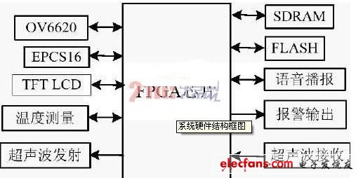
Figure 1 Block diagram of system hardware structure
1. 2.2 Design of main functional modules
2. 2.2.1 Image acquisition and conversion circuit
The block diagram of the image acquisition and conversion circuit is shown in Figure 2. The YCrCb4: 2: 2 format data output by the image sensor OV6620 is converted into YCrCb4: 4: 4 format data by the deinterleaving circuit, and sent to the color space conversion circuit to complete the data format conversion, and then stored in the buffer RAM. The following focuses on the color space conversion circuit.
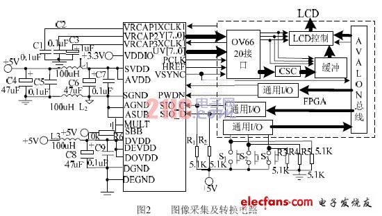
The image sensor ov6620 outputs data in YCrCb4: 2: 2 format, and the LCD screen used in the design requires input of RGB888 format data, so a color space conversion circuit is required to complete this conversion. The conversion formula is shown in equation (1).
The RGB in the conversion result is an 8-bit unsigned number, with a value range of 0 to 255, so the operation result is 0 for negative numbers; the operation result exceeds 255 and 255. This will introduce errors, but it has little effect on the display of the image. Using VerilogHDL to complete the design of the circuit, when the YCrCb values ​​are 197, 92, and 232, respectively, the GRB output (with delay) is 186, 146, and 255, which is consistent with the results calculated according to formula (1).
2.2.2 Ultrasonic transmission and reception
If higher frequency ultrasound is used in ultrasonic ranging, it will decay faster due to larger air absorption, so the measuring distance is shorter. For example, using 40kHz ultrasonic wave, the range of measurement generally does not exceed 5m. Since the absorption of ultrasonic waves by air is proportional to the square of the ultrasonic frequency, reducing the frequency of ultrasonic waves can increase the range of the distance measurement. But if the frequency is too low, the absolute error of distance measurement is larger [4]. In order to take into account both the range and accuracy of the distance measurement, two ultrasonic distance measurements of 40kHz and 25kHz are used in the design. The measurement principle is: first output 10 40kHz ultrasonic pulses, and then output 8 25kHz ultrasonic pulses. Because high-frequency ultrasonic waves are sent out first, for the same target, the echo reaches the CPU first, so for short-range targets, first use high Low-frequency ultrasonic detection, the absolute error of measurement is small; for distant targets, the high-frequency ultrasonic wave is absorbed by the air and greatly attenuated, so the echo is only low-frequency ultrasonic. Acceptable. The received ultrasonic signal is sent to the PIO port of NiosII after processing such as amplification and comparison, and the PIO port is interrupted. The ultrasonic propagation time is obtained by executing the interrupt service program, and then the distance of the obstacle is calculated according to the measured ambient temperature. Calculate the relative speed between the two measurements. Only 25kHz ultrasonic transmitting and receiving circuits are shown here, as shown in Figure 3.
Foresee more exciting information about the rearview mirror, please poke right: http: //
The Transient Voltage Suppressor (TVS) is a high-performance protection device in the form of a diode. When the two poles of a Tvs Diode are subjected to a reverse transient high-energy shock, it can change the high impedance between the two poles to a low impedance at a speed of the order of 10 minus 12 powers, absorbing up to several kilowatts of surge power. The voltage between the two poles is clamped to a predetermined value, effectively protecting the precision components in the electronic circuit from various surge pulses.
Transient Voltage Suppressor
Transient Voltage Suppressor,Tvs Diode,Tvs Diode Ethernet,Tvs Diode For Automotive
Dongguan Agertech Technology Co., Ltd. , https://www.agertechcomponents.com