At present, the home network mainly realizes control and access to various smart appliances directly through the dual-core cable. It is troublesome to install wiring in this way. In order to overcome the trouble of installing and wiring, the wireless transmission method is used to realize various control and access within the home network .
1 System structure
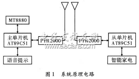
This system first uses the DTMF transceiver circuit chip MT8880 to realize remote access through the telephone line, and then uses the serial port of the main single-chip microcomputer AT89C51 to transmit various access and control information to the wireless digital transmission MODEM chip PTR2000, and realizes the wireless transmission of data through the PTR2000; The receiving end of the smart home appliance first receives the control and access information sent by the host through the external PTR2000, and then transmits it to the slave AT89C51 to realize the control of various functions. System principle circuit, as shown in Figure 1.
2 Implementation method of telephone remote access
This system remote access uses DTMF transceiver chip MT8880 to realize telephone remote access. MT8880 is a CMOS large-scale integrated circuit with low power consumption, and the sending and receiving circuits are concentrated in one chip, which is easy to interface with a microcomputer and convenient to use. Because the transmission part uses a switched capacitor D / A converter, the DTMF signal distortion is small and the frequency accuracy is high. The on-chip counter accurately times the duty time of the dual audio mode. And can detect telephone signal tone.
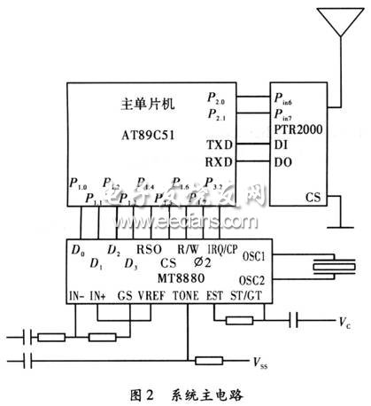
P1.0 ~ P1.3 of the main single-chip AT89C51 are respectively connected to D0 ~ D3 of MT8880; P1.4 ~ P1 of the single-chip AT89C51 are respectively connected to RSO, CS, R / W, 02 of MT8880, and P3 of the single-chip AT89C51. 2 Connect the IRQ / CP of MT8880, the specific circuit, as shown in Figure 2.
3 Realization method of wireless transmission
This system adopts ultra-small, ultra-low power, high-rate wireless digital transmission MODEM chip PTR2000 to realize wireless transmission of data. The operating frequency of PTR2000 is 433 MHz, which is an internationally-used digital transmission frequency band. It adopts FSK modulation and DDS + PLL frequency synthesis technology. It has two channels and the operating speed can reach up to 20 kB / s. 2.7 V), low power consumption, low transmit power (+10 dBm), high receiving sensitivity (-105 dBm) design, no need to apply for a license.
PTR2000 is simple and reliable, with only 7 external pins. The control functions of each pin are as follows:
Pin1: Vcc positive power supply, 2.7 ~ 5.25 V;
Pin2: CS channel selection, CS = 0 selects working channel 1 (433.92 MHz), CS = 1 selects working channel 2 (434.33 MHz);
Pin3: DO data output;
Pin4: DI data input;
Pin5: GND power ground;
Pin6: PWR energy-saving control, PWR = 1 is the normal working state, PWR = 0 is the standby micro power consumption state;
Pin7: TEXN working mode selection, when TEXN = 1, the module is in transmitting state, and when TEXN = 0, the module is in receiving state.
The interface circuit of the main single-chip AT89C51 and its external PTR2000, as shown in Figure 2. The CS of the PTR2000 is directly connected to the ground, using working channel 1, which is 433.92 MHz. Pin6 of PTR2000 is connected to P2.0 of the single-chip microcomputer, and Pin7 of PTR2000 is connected to P2.1 of the single-chip microcomputer. The TXD and RXD of the main single-chip AT89C51 are connected to the DI and DO terminals of PTR2000 respectively. The interface circuit from the MCU and its external PTR2000 is the same.
The master MCU AT89C51 sends the data to the PTR2000 according to the control requirements, and then the PTR2000 transmits the data after FSK modulation, and after receiving the FSK modulation signal from the external PTR2000 of the slave AT89C51, it first demodulates and outputs the control information to the slave AT89C51 The slave AT89C51 controls the work of smart home appliances.
Because the single-chip AT89C51 has multi-computer communication function, the multi-computer communication is realized by using the serial port of the single-chip AT89C51. When the SM2 bit of an AT89C51 MCU is 1, the MCU only receives the address frame and ignores the data frame, and when the SM2 bit is 0, it receives all the information sent. If the master wants to communicate with a target slave, the master sets Pin7 = 1 of its external PTR2000, sends a frame of address information of the target slave to all slaves, and then sets the Pin7 = 0 of its external PTR2000 to receive The response information sent by the machine. After receiving the address frame, each slave responds to the serial port interrupt and compares its own address with the target slave address. If the two are the same, the slave is the target slave, set Pin7 of the external PTR2000 of the slave to send a response message to the host, and then set SM2 = 0 of the slave and Pin7 of the external PTR2000 to receive subsequent control Information and data. If the two are different, the slave is not the target slave, and the SM2 = 1 of the slave is still maintained, and the Pin7 = 0 of the external PTR2000 is ignored, and the control information and data sent by the master are ignored. After the master receives the response information sent from the slave, it starts to send control information and data.
5 Burner Gas Hob,5 Burner Gas Cooker,5 Burner Hob,Glass Gas Hobs
Xunda Science & Technology Group Co.ltd , https://www.xundatec.com