The rapid development of LED lighting means that a large number of IC devices are needed to provide power control for LEDs. In the current energy-saving era, in order to control the LED current, switching LED drivers have already begun to replace high-power linear devices. From flashing lights to street lights to stadium scoreboards, these products require precisely controlled LED light output (ie, luminous flux).
Luminous flux (unit lumens) is a measure of useful work emitted by a light source. This performance index is a weighted function of the energy of all wavelengths and the visible light area that corresponds specifically to the response of the human eye. The luminous flux of the LED is proportional to the size of the drive current. In many cases, real-time changes in light output must be achieved by changing the LED drive current, which is commonly referred to as dimming control.
Color control is also important in many dimming applications. The usual method of manufacturing high-brightness white LEDs is to coat a layer of phosphor hemisphere on the blue-emitting LED chip. The final emitted light will appear as white light at a certain color temperature. Color temperature is a performance indicator used to describe the color of light compared with the reference color on the blackbody curve. LED manufacturers have developed a nominal color temperature to represent white LEDs; but in fact it is easily changed by the influence of forward current, junction temperature and product life. Most color LEDs do not contain phosphors, they do not consider the color temperature, they only emit light of a specific wavelength, but they are affected by wavelength shifts.
technical background
Figure 1 shows the DC / DC switching LED driver in a compensated topology. In this topology, the input voltage Vin is higher than the output voltage VOUT (the voltage on the LED and RSNS). The energy is through a controlled switch (connected to the inside of LM3406 in Figure 1), diode D1 and inductor L1. Processing and passing between input and output. Generally, energy transfer occurs between the conversion frequency of 50KHZ to 1MHZ, depending on the actual application. By monitoring the average voltage value on the sense resistor RSNS flowing through the CS pin, the LED current can be controlled. The duty cycle of the internal conversion driver is dynamically changed, and the CS pin is adjusted by increasing or decreasing the LED current.
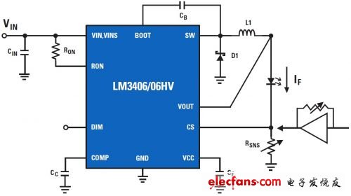
Fig. 1. Switching LED driver
There are two common methods for dimming control of switch-mode LED drivers: pulse width modulation dimming (pulse width modulation) and analog dimming. Both methods are achieved by controlling the time-averaged current flowing through the LED, but there are many differences between the two methods. In addition to the functional differences to be discussed below, the advantages and problems of the two methods are also listed in Table 1.
Analog dimming
Using switch-mode drivers for analog dimming is achieved by adjusting the nominal LED current. Theoretically, LM3406 is used to simulate dimming in Figure 1, which can be achieved by adjusting RSNS. But in actual operation, the value of RSNS is very small (less than 1Ω), which is not conducive to the power dissipation of the resistor. No standard potentiometer can provide such a small variable resistance. Conversely, there is a more complex technique that can directly control the nominal LED current by using a fixed detection resistor. As shown in Figure 1, an operational amplifier can be placed between the CS pin and RSNS to buffer and amplify the detection voltage. A higher resistance potentiometer can be placed on the feedback loop from input to output to adjust the effective sensing voltage value, so as to achieve the purpose of analog dimming the LED.
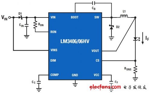
Fig. 2. Two-line pulse width modulation and pulse width modulation dimming application
The main disadvantage of analog dimming is that the color temperature is large, and the wavelength corresponding to the average LED current is shifted. Depending on the actual application, this problem is critical for some applications, while others are not. For example, for a standard, low-cost, white LED flash covered with phosphor coating, the problem of color temperature shift is almost negligible. In contrast, backlit displays that use RGB (red, green, and blue) LEDs do not allow any wavelength shift when simulating dimming. Analog dimming is relatively simple and low cost, which makes it very popular in some specific application areas, of course not all applications.
PMW dimming
Contrary to analog dimming, pulse-width modulation dimming is not regulated by the nominal current, but by switching on and off with a switching controller below the switching frequency. It produces a modulated output current whose average value is equal to the fixed LED nominal current value multiplied by the duty cycle of the pulse width modulated drive signal. The frequency range of pulse width modulation dimming is from 100 times / Hz to 10 times / kHz. This frequency must be faster than the human eye perceives, so that stroboscopic phenomenon can be avoided. In general, its frequency is limited to greater than or equal to 200HZ.
Through pulse width modulation dimming, the LED current is zero or at the nominal current level, which greatly improves the color shift phenomenon during analog dimming. This technology is the first choice for applications that require precise color control. The disadvantage is that the noise of the switch will increase during the pulse width modulation of the LED current. Of course, generating a pulse width modulated input signal will also increase the cost and product design will be more complicated.
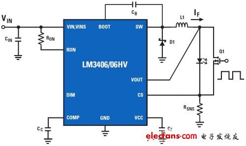
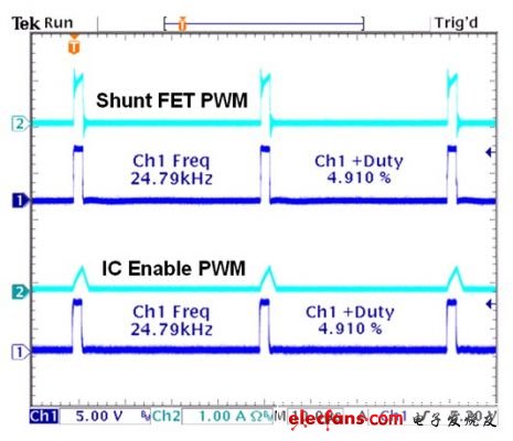
Fig. 3. Pulse width modulation and pulse width modulation dimming application and generated waveform of parallel parallel FET
As shown in Figure 3 (a), many LED drivers feature a dedicated pulse width modulation dimming pin. This DIM pin can adapt to a very wide pulse width modulation frequency and amplitude, allowing a simple interface to connect external logic circuits. The DIM function turns off the internal switch, which keeps the internal bias circuit running, ensures that no output is provided to the LED driver, and avoids IC restart delays. Minimizing the delay time allows the driver to obtain a wider dimming range. The minimum achievable duty cycle during the execution of such pulse width modulation dimming is limited by the rise time and decay time (conversion rate) of the inductor shown in FIG. 3 (b). Pulse width modulation dimming through the DIM pin can be used in many applications ranging from automotive headlights to general-purpose spotlights.
For more complex applications such as TV backlights, a larger dimming range is required. Only using parallel FET dimming as shown in Figure 3 (a) is possible. In this configuration, the switchable LED driver continuously regulates the output current. The pulse width modulation dimming signal controls the switching gate of the LED load. The LED current flowing through the switch is redirected by the switch on and off, and flows backward through the LED within the required duty cycle. The effect is basically the same as the DIM pin used for pulse width modulation dimming. In this PMW dimming, the duty cycle controls the average LED current. The rise and fall time of LED current is a command to make the amplitude faster, they are not dependent on the conversion rate of the inductor. Figure 3 (b) shows how to achieve a smaller minimum duty cycle, which greatly improves the dimming range.
Two-line dimming
Two-line pulse width modulation dimming is a very popular interior lighting technology. This technology was initially used for incandescent lamp loads. By reducing the average voltage through a resistive load, you can directly adjust its indoor light source to achieve dimming. Because the automotive industry is still in the transition to applying LEDs, the existing architecture is still attractive to some manufacturers. There is a problem in the design of switching power supply, you can adjust the output regardless of the input state. In order to use the dimming information embedded in the power supply, it is necessary to decode the dimming angle.
Figure 2 shows a method for two-line dimming using a switched LED driver. As VIN rises and falls, the VINS pin monitors the duty cycle and converts the pulse-width modulation waveform to internal switch modulation. The dimming effect is the same as the pulse width modulation dimming through the DIM pin. The disadvantage of this method is that when the input power is turned off at each dimming cycle, the input capacitor CIN must provide input power. In addition, the high-voltage diode D1 must ensure that the VINS pin can detect the modulation signal.
Dimming and efficiency
LED light efficiency can be simply defined as the visible output power expressed in lumens compared to the input electrical power expressed in watts (in lumens / W). All electrical power that enters the LED but fails to generate visible light is converted into heat or invisible electromagnetic radiation. It is well known that all LEDs have higher luminous efficiency (at lower output power) when driven with forward current. Fig. 7 illustrates the common relationship between LED forward current and luminous flux. When the index deviates from the ideal line, the light effect will decrease accordingly.
In Figure 7, we can see that at a lower dimming level, compared to pulse-width modulation dimming, the analog dimming LED has a higher light efficiency. At a lower duty cycle, we will consider using pulse width modulation dimming. The peak LED current is much larger than the time-averaged LED current. On the other hand, analog dimming LEDs are only suitable for average current levels.
Composite dimming function
National Semiconductor's LM3409 is a uniquely designed buck LED controller that can easily provide support for analog dimming and pulse width modulation dimming. Analog dimming and pulse width modulation dimming can be performed separately, or some simple operations can be synchronized in a complex dimming mode. Figure 4 illustrates a typical analog dimming application using the LM3409. There are four ways to achieve LED dimming using this device.
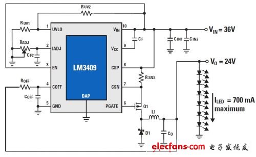
Fig. 4. Analog dimming using potentiometer
1. When the power supply voltage changes from 0V to 1.24V, directly drive the IADJ pin to simulate dimming
2. Install a potentiometer between the IADJ pin and Gnd to simulate dimming
3. Use the EN pin for pulse width modulation dimming
4. Pulse width modulation dimming through external shunt FET
LM3409 is a damping accessory. The main switch Q1 is opened, and energy is transferred from the input to the output. When the switch current reaches the peak threshold, Q1 turns off. Then a stable turn-off timing switch proportional to the output voltage will determine the turn-off time. Analog dimming can be performed by changing the internal peak sensing threshold current in the range of 0-248mV. If the IADJ pin is left floating, the internal 5uA current source pin voltage is biased to 1.24V, so that the LED current through the detection resistor RSNS will peak at 248mV. . If a potentiometer is grounded from the IADJ (GND) and the 5uA power supply is biased to the RADJ, a voltage is generated that will change the internal current sensing threshold. In the same way, the IADJ pin can be driven with only a DC voltage from 0-1.24V, calibrating the current sensing threshold from 0-248mV.
Figure 5 is a plan view of measuring the LED current and the resistance value of the potentiometer from the IADJ pin to GND. At very low dimming amplitudes, the transfer function of LED current to potentiometer resistance is almost linear. Due to the internal 2.5V clamping voltage shown in Figure 4, the maximum current is limited to less than 1A.
The pulse width modulation dimming of LM3409 is the same as LM3406, except that LM3406 uses a dedicated DIM pin, while LM3409 uses the EN pin. The EN pin is a logic input. This logic input uses a pulse-width modulated input signal to turn the main FET Q1 on and off. The only difference between LM3409 and LM3406 is that if the lead wire of EN pin is long enough and the position is low, LM3409 will be turned off completely. LM3409 can also achieve parallel shunt FET dimming.
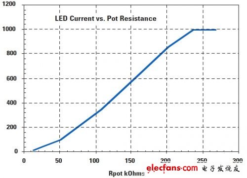
Fig 5. Current and potentiometer resistance
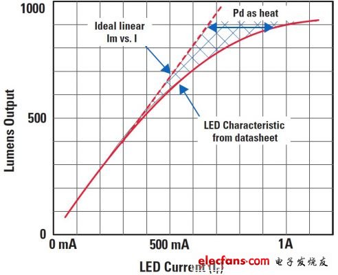
Fig. 7. Current and luminous flux
Electric Hand Air Pump,Volleyball Air Pump,Portable Ball Air Pump,Ball Air Compressor
SHENZHEN SMARTNEWO TECHNOLOGY CO,. LTD , https://www.newopump.com