As microelectronics and computer technologies continue to evolve, the landscape of electrical equipment is undergoing significant transformation. Traditional devices, primarily based on strong electrical currents and appliances, are now evolving into advanced microelectronic systems with enhanced digital capabilities and multifunctional features. This shift has led to the emergence of numerous single-chip solutions that are replacing conventional electrical control products. A single-chip microcomputer, operating on a memory-programmed control system, achieves its functionality through software instructions, while its hardware configuration remains adaptable. Consequently, when production processes change, there’s no need to redesign the wiring or installations, making it easier to accommodate product modifications and custom orders.
In modern control systems, the signals utilized by traditional electrical equipment must be converted into digital formats compatible with the input/output ports of microcontrollers. For instance, users typically input various control signals, such as limit switches, operation buttons, selection switches, and sensor outputs, into the single-chip microcomputer. These signals are then converted into formats that the microcontroller can process through an input circuit. On the output side, the microcontroller's weak electric control signals are amplified and transformed into stronger signals suitable for driving actuators like power tubes, solenoid valves, relays, contactors, and motors. This facilitates the overall control system’s performance.
Given these characteristics of electrical control products, this paper explores the design methodologies for common drive and isolation circuits for various single-chip I/O ports. This approach is crucial for designing efficient electrical control systems, enhancing circuit interfacing capabilities, and improving system stability and anti-interference properties.
Firstly, let’s consider the design of input circuits. Most control inputs are typically received in the form of switch signals. Based on engineering practices, a low-level effect is often preferred over a high-level effect for the input signals. For example, pressing a switch sends a low-level command, while releasing it produces a high-level output. This setup enhances noise immunity.
However, given the susceptibility of TTL levels to external interference, especially during long-distance transmissions, the input signal can be elevated to +24V. This conversion into a higher voltage signal before entering the microcontroller not only improves noise resistance but also ensures more reliable switch contacts. Additionally, to protect against external spikes and static electricity, an anti-pulse diode can be integrated into the input to form a bidirectional protection circuit. This arrangement ensures that regardless of the polarity of the input voltage, the amplitude of the voltage is restricted within a safe range.
Another common method involves using an optocoupler isolation circuit. As illustrated in Figure 4, an input current-limiting resistor ensures the LED current in the optocoupler stays within a safe range of 10-20mA. By transmitting signals via light, the circuit achieves complete electrical isolation. Furthermore, the low forward resistance of the LED and the high internal resistance of the external interference source significantly reduce the amount of interference noise reaching the input terminal, preventing ground loops or cross-talk.
For additional reliability, simple solutions include connecting a capacitor in parallel with the input to ground to absorb interference pulses or adding a metal film resistor in series to limit the peak current flowing into the port.
Turning to output circuit designs, the output port of a microcontroller is often limited by its driving capability. Hence, a dedicated interface chip is frequently required. Depending on the control object, output requirements vary in terms of voltage, current, switching frequency, waveform rise/fall rates, and isolation against interference. Here are some typical circuit implementations for driving power from a microcontroller.
One approach is direct coupling. However, care must be taken to avoid circuits like the one shown in Figure 5, as it can lead to issues such as excessive heat generation and instability. Instead, a direct coupled output circuit using T1 and T2 to drive T3, as depicted in Figure 6, is preferable. This setup ensures proper switching behavior and reduces losses effectively.
For scenarios requiring higher switching speeds, TTL or CMOS devices with open collectors can be used, as shown in Figure 7(a). Adding a collector load resistor boosts the drive voltage. To further enhance switching speeds, alternative circuits like those in Figures 7(b) and 7(c) can be employed. These improved circuits offer faster turn-on and turn-off times, minimizing dynamic losses.
Pulse transformer coupling offers another option, isolating the signal and energy transfer through electromagnetic means. This method allows for floating output signals that can be directly coupled with high-voltage components, as seen in Figure 8. The pulse source's frequency must be at least ten times higher than the microcontroller's output frequency to ensure effective signal transmission.
Lastly, photoelectric coupling using optocouplers is useful for transmitting both linear and switching signals. While they provide excellent isolation, their slow response times can limit usage frequency.
In conclusion, while many resources discuss single-chip microcomputer interface technologies, challenges such as large drive currents, slow switching speeds, and poor interference resistance persist. Thus, exploring diverse circuit solutions remains essential for optimizing the reliability and efficiency of single-chip electrical control systems.
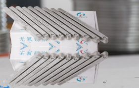
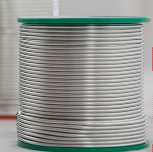
Solder Bar
Solder Wire/bar is an indispensable material for the manufacture of electronic products .Tin wire,TIn bar and tin paste are the most widely used electronic welding materials,the technical level depends on the performance of solder joints and welding process performance.
Product specification: Ñ„12*330mm
295*20*13mm
Product Features:
Smooth surface,neat coiling,beautiful appearance,uniform distribution of additives,good continuity.
Less splash of additives in welding process,good mobility,good wettability,less smoke,less oxide slag,bright welding spots.
Widely used in a variety of wave slidering and manual welding of television,audio capacitors,circuit boadrds and communications equipment.
Including SnCu.SnAg.SnAgCu,SnAgCuSb.SnAgBi series.


Solder Bar,Solder Wire Bar,Silver Solder Bar,Lead-Free Tin Solder Bar
Shaoxing Tianlong Tin Materials Co.,Ltd. , https://www.tianlongspray.com

