Many potters who entered the automation industry often do not understand the so-called second-, third-, and fourth-line systems, but they are not happy to show their spirit of shameless inquiry. Xiao Bian expresses his heart-breaking pains. Apart from being sad, he must share with you. This article. “
First, talk about the difference between the transmitter and the sensor: The sensor is a generic term for a device or device that can be measured and converted into a usable output signal according to a certain rule. It is usually composed of a sensitive element and a conversion element. When the output of the sensor is a specified standard signal, it is called a transmitter.
The name of a few lines is only after the birth of a two-wire transmitter. The two-wire system, the three-wire system, and the four-wire system that we discussed refer to the transmitters that output analog DC current signals. Their working principles and structural differences do not refer to the wiring of the transmitter.
Four-wire system
The first to appear is the four-wire transmitter; that is, two lines are responsible for the supply of power, while the other two lines are responsible for outputting signals that are converted and amplified (such as voltage, current, etc.). The four-wire connection is shown in the figure below:
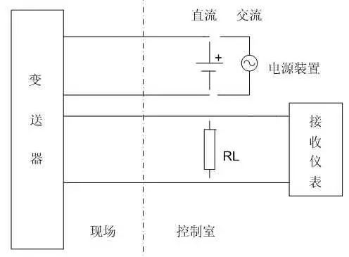
Most of the four-wire transmitters are 220VAC, but also have 24VDC power supply. The output signal has 4-20mADC, the load resistance is 250Ω, or 0-10mADC, the load resistance is 0-1.5KΩ; There are also mA and mV signals, but the load resistance or input resistance is different because of the output circuit different. (ps: AC will affect signal accuracy)
Application: Digital display, electromagnetic flow meter transmission output is four-wire system.
Three-wire system
The so-called three-wire system is that the positive terminal of the power supply uses a wire, and the positive terminal of the signal output uses a single wire, and the negative terminal of the power supply and the negative terminal of the signal share a single wire. The three restrictions wiring as shown below:
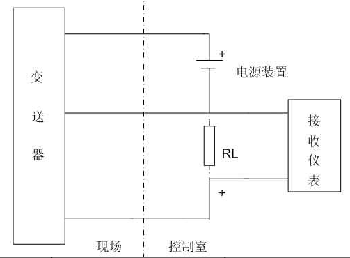
Most of the three-wire transmitter power supply is 24VDC, output signal 4-20mADC, load resistance is 250Ω or 0-10mADC, load resistance is 0-1.5KΩ; there are also mA and mV signals, but the load resistance or input resistance, due to The output circuit is different and the value is different.
Application: Transmission output of voltage output is generally three-wire system.
Two-wire system
Using the loop-powered mode, the 4-20mA current itself can power the transmitter. The transmitter is equivalent to a special load in the circuit. The display instrument only needs to be in the circuit. That is, the power supply and the load are connected in series and there is a common point, and the signal connection and power supply between the on-site transmitter and the control room instrument use only two wires. The two wires are both the power line and the signal line. The second limit wiring is as shown below:
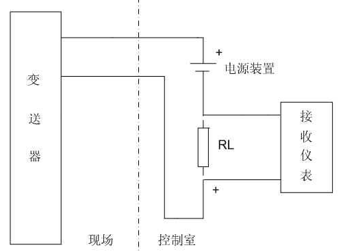
The two-wire transmitter powers 24VDC, the output signal is 4-20mADC, the load resistance is 250Ω, and the negative line potential of the 24V power supply is the lowest, which is the signal common line.
(ps: The input receiving instrument is a current signal. If the resistance RL is connected in parallel, the voltage signal is received.)
Applications: Temperature transmitters, 4-20mA output pressure transmitters are two-wire systems.
In industrial applications, measurement points are generally on site, and display devices or control devices are generally on the control room or control cabinet. The distance between the two may be tens to hundreds of meters. Calculated by the distance of one hundred meters, the elimination of two signal transmission lines means that the cost is reduced by nearly one hundred yuan! In addition, four-wire transmitters and three-wire transmitters must use expensive shielded wires due to asymmetrical currents in the wire, and two-wire transmitters can use very inexpensive twisted-pair wires, so two wires are used in applications. The transmitter must be the first choice.
Then what are the restrictions for using the two-wire system?
To implement a two-wire transmitter, the following conditions must be met at the same time:
1
V ≤ Emin - ImaxRLmax (The transmitter output voltage V is equal to the specified minimum supply voltage minus the voltage drop across the load resistance and the transmission line resistance of the current.)
2
I ≤ Imin (The transmitter's normal operating current I must be less than or equal to the transmitter's output current.)
3
P<Imin(Emin-IminRLmax) (The minimum power consumption P of the transmitter cannot exceed the above formula, usually <90mW. where: Emin=lowest supply voltage, for most instruments Emin=24(1-5%)= 22.8V, 5% is the allowable negative change of the 24V power supply; Imax = 20mA; Imin = 4mA; RLmax = 250Ω + transmission line resistance.)
Due to the popularization and application of the 4-20mADC (1-5 VDC) signal system, in order to facilitate connection in the application of control systems, the unified signal system is required. For this reason, some non-electric unit combination instruments, such as on-line analysis, mechanical quantity, are required. Power meters and other instruments can use an output signal of 4-20mADC, but due to complicated conversion circuits and high power consumption, it is difficult to fully satisfy the above three conditions, and the two-wire system cannot be used. Only external power supplies can be used. The method to do a 4-wire transmitter with 4-20mADC output.
Compared with the four- and three-wire systems, what are the advantages of the two-wire system?
1
Easily affected by parasitic thermocouples and resistance drop and temperature drift along the wire resistance, very inexpensive and thinner wires can be used; a large number of cables and installation costs can be saved;
2
When the output resistance of the current source is large enough, the voltage in the wire loop induced by the magnetic field coupling will not have a significant impact, because the current caused by the interference source is extremely small, generally using a twisted pair cable to reduce the interference; two wire system and The three-wire system must use shielded wire. The shielded wire shield must be properly grounded.
3
Capacitive interference can cause receiver-related resistance errors. For a 4 to 20 mA two-wire loop, the receiver resistance is typically 250 Ω (sampling Uout = 1 to 5 V). This resistance is small enough to produce significant errors, so it is permissible The length of the wire is longer and farther than the voltage telemetry system;
4
Each single reading device or recording device can switch between different channels with different lengths of wire. It does not cause the difference in accuracy due to the unequal length of the wire, and achieves distributed acquisition. The benefits of distributed acquisition are: scattered collection, Centralized control....
5
Using 4mA for zero level makes it easy to judge open circuit and short circuit or sensor damage (0mA state).
6
It is very easy to add one or two lightning protection devices to the two-wire output port, which is conducive to safe lightning protection and explosion protection.
to sum up
The four-wire system consists of two signal lines and two power supply lines. The signal line and the power supply line are separated. The accuracy is best, the load capacity is the strongest, the anti-jamming ability is the worst, the circuit structure is the most complicated, and the cost is relatively high; while the three-wire system is The signal line and the power supply line share a positive or negative polarity. The accuracy is secondarily, the anti-interference ability is better than the four-wire system, the circuit structure is more complex, the cost is lower than the four-wire system, and the two-wire system is the two lines that do both , And do signal lines, the largest error, weak load capacity, strong anti-interference ability, simple circuit structure, the lowest cost, the widest range of applications; In addition two-wire system can only output mA current signal, three-wire and four-wire system do not have this Limitations, most transmitters now use two-wire systems.
Cummins 0-20KW Diesel Generator
Cummins 0-20Kw Diesel Generator,Cummins Portable Power Generator,Cummins Open Type Power Generator,Cummins Container Power Generator
Shanghai Kosta Electric Co., Ltd. , https://www.ksdpower.com