When working in master-slave mode with a 51 single-chip microcontroller, the first step is to configure the serial port into mode 3, which supports variable baud rate and allows for more complex communication protocols. The SCON register is set as follows: SM0 = 1 and SM1 = 1, which enables mode 3. Both the master and slave must be in this mode to communicate effectively.
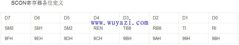
Mode 3 is similar to mode 2 but includes a variable baud rate, making it more flexible for different applications. In mode 2, the serial port sends or receives 11 bits: one start bit, eight data bits, one programmable bit (TB8), and one stop bit. When sending, the programmer sets TB8 to either a parity bit or a data flag before writing the data to SBUF. The transmission begins when the instruction that uses SBUF as the destination is executed. The 8-bit data and the 9th bit (TB8) are then sent through the TXD pin (P3.1).
For receiving, the REN bit must be set to 1 to enable reception, and the RI flag must be cleared to 0. Depending on the state of SM2 and RB8, the serial port determines whether to set RI to 1 and trigger an interrupt. If SM2 is 0, the serial port will always receive any incoming data. If SM2 is 1, the serial port only receives data when RB8 is 1 (indicating an address frame), otherwise, it ignores the data.
When the host sends an address, it sets TB8 to 1, and when sending data, it sets TB8 to 0. This helps the slave identify whether it's receiving an address or actual data. The frame structure for sending is shown below:

For example, if the host wants to send "1234" to a slave with address 1, it calls the function: TXdata(1, "1234$"); where the "$" symbol is used as the end-of-message marker.
Here's how the function might look:
  void TXdata(uchar addr, uchar *str) {
    TB8 = 1; // Send address
    SBUF = addr; // Send the address
    while(!TI); // Wait until transmission is complete
    TI = 0;

    TB8 = 0; // Send data
    while(*str != '\0') { // Send each character
      SBUF = (*str);
      while(!TI);
      TI = 0;
      str++;
    }
  }
On the slave side, the configuration involves setting SM2 to 1 initially so that it only responds to address frames. Once the correct address is received, SM2 is set to 0 to allow normal data reception.
Here’s an example of the serial interrupt service routine:
  void chuan() interrupt 4 // Serial interrupt service function
  {
    ES = 0; // Disable serial interrupt
    if (RI) // Check if data was received
    {
      RXData = SBUF;
      if (RXstart)
      {
        if (RXData != '$')
        {
          Temp[j] = RXData;
          j++;
        }
        else
        {
          RXstart = 0;
          SM2 = 1;
          j = 0;
        }
      }

      if (RXData == 1) // Check if the address matches
      {
        RXstart = 1;
        SM2 = 0;
      }
    }
    RI = 0;
    ES = 1;
  }
For the serial port initialization, the following code is commonly used for 89S51, 52, or STC12Cxxx microcontrollers with an 11.0592MHz crystal at 9600bps:
  void UART_init()
  {
    TMOD = 0x20; // Timer 1, mode 2
    TH1 = 0xFD; // Set for 9600bps
    TL1 = 0xFD;
    REN = 1; // Enable receive
    SM0 = 1;
    SM1 = 1; // Mode 3
    SM2 = 1; // Receive only address
    ES = 1; // Enable serial interrupt
    TR1 = 1; // Start timer
    EA = 1; // Enable global interrupts
  }
Finally, some important notes about wiring and communication:

- Communication between slaves must go through the master.
- Each slave's TXD should be set to open-drain output, not push-pull.
- The communication bus should not exceed 2 meters in length for reliable performance.
Pin Header Connector,Pin Header Female,Male Header Pins,Right Angle Pin Header
Cixi Xinke Electronic Technology Co., Ltd. , https://www.cxxinke.com