In this tutorial, we'll explore the master-slave communication using the 8051 series microcontroller. The key is to configure the serial port correctly for mode 3, which allows for variable baud rate and 11-bit asynchronous communication.
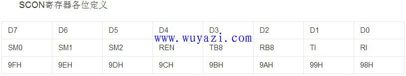
First, set the serial port working mode to mode 3 by configuring SCON: SM0=1 and SM1=1. This ensures both the master and the slave are operating in the same mode. A diagram illustrating the configuration is provided below:
 When sending data, the master should set TB8 to 1 when sending an address, and 0 when sending actual data. For example, if the host wants to send "1234" to a device with address 1, it would call a function like `TXdata(1, "1234$");`.
The function `TXdata` handles the transmission process. It sets TB8 to 1 to send the address first, then clears TB8 to 0 for the data. Each character is sent one at a time through the serial port.
On the slave side, the initialization process is crucial. The slave must be configured to receive only when TB8 is 1, which indicates an address frame. Once the correct address is received, the slave switches to data mode by setting SM2 to 0.
An interrupt service routine (ISR) manages the reception of data. It checks whether the received data is an address or a data frame, and accordingly enables or disables the receiving mode. Here's an example of the ISR:
When sending data, the master should set TB8 to 1 when sending an address, and 0 when sending actual data. For example, if the host wants to send "1234" to a device with address 1, it would call a function like `TXdata(1, "1234$");`.
The function `TXdata` handles the transmission process. It sets TB8 to 1 to send the address first, then clears TB8 to 0 for the data. Each character is sent one at a time through the serial port.
On the slave side, the initialization process is crucial. The slave must be configured to receive only when TB8 is 1, which indicates an address frame. Once the correct address is received, the slave switches to data mode by setting SM2 to 0.
An interrupt service routine (ISR) manages the reception of data. It checks whether the received data is an address or a data frame, and accordingly enables or disables the receiving mode. Here's an example of the ISR:

    void chuan() interrupt 4
    {
        ES = 0;
        if (RI)
        {
            RXData = SBUF;
            if (RXstart)
            {
                if (RXData != '$')
                {
                    Temp[j] = RXData;
                    j++;
                }
                else
                {
                    RXstart = 0;
                    SM2 = 1;
                    j = 0;
                }
            }
            if (RXData == 1)
            {
                RXstart = 1;
                SM2 = 0;
            }
        }
        RI = 0;
        ES = 1;
    }
The serial port initialization function configures Timer 1 for baud rate generation and sets up the serial port for mode 3 with interrupts enabled.
    void UART_init()
    {
        TMOD = 0x20;
        TH1 = 0xfd;
        TL1 = 0xfd;
        REN = 1;
        SM0 = 1;
        SM1 = 1;
        SM2 = 1;
        ES = 1;
        TR1 = 1;
        EA = 1;
    }
Finally, here’s a wiring diagram and some important notes:
 - Communication between slaves must go through the master.
- Each slave’s TXD should be set to open-drain output.
- The communication bus length should not exceed 2 meters for reliable operation.
By following these steps and configurations, you can successfully implement a master-slave communication system using 8051 microcontrollers.
- Communication between slaves must go through the master.
- Each slave’s TXD should be set to open-drain output.
- The communication bus length should not exceed 2 meters for reliable operation.
By following these steps and configurations, you can successfully implement a master-slave communication system using 8051 microcontrollers.
Cixi Xinke Electronic Technology Co., Ltd. , https://www.cxxinke.com