The requirements for in-vehicle power management are becoming more demanding, requiring power supplies to operate over a wider range of input voltages, higher currents, and higher temperature extremes. These requirements will make the switch mode power supply design mainstream because of the greater flexibility, better configurability, and higher thermal efficiency of this power supply design.
This article refers to the address: http://
The core component of the switch mode power supply is the DC-DC converter. Today's on-board converters must be able to support a variety of operating conditions, such as low voltage operation (ie cold start) and positive transient survivability (ie, suppressed or unsuppressed load dump conditions). The increased load requirements of the emergence of in-vehicle subsystems have made the design of these data more complex. This article will provide designers with a brief introduction to automotive power requirements and introduce a new TDC74100 DC-DC converter recently introduced by TI.
Transient protection
Load dump
Almost all electronic components and circuits that are directly connected to the car's battery are protected from damage, transient voltage (up to 60V), and reverse voltage conditions. For these electronic circuits, it must be able to withstand a certain degree of overvoltage on the power line, which is also a common requirement. This is especially true for in-vehicle systems that require the mains input of any particular in-vehicle electronic system to operate under a variety of transient voltage conditions, including alternator load dumps.
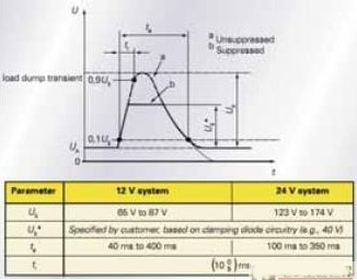
Since the alternator control loop is not fast enough to shut down, it produces a high output voltage pulse when the battery voltage is removed. Normally, at a central location in the car, this high energy pulse is controlled (or suppressed) to a lower voltage range. However, automakers still specify to their suppliers the residual overvoltage that may occur at their power input. This situation is different among different car manufacturers, but the standard peak of the car is about 40V, while the standard peak of the commercial car is about 60V. The duration of a typical throw load pulse is a few tenths of a second. The following figure (Figure 1) shows a typical pulse for this load dump state.
Cold start in dashboard applications
The demand for power management chips in the automotive environment is increasing. One of these requirements is that the power management IC needs to operate over a wide voltage offset range, and electronic systems that are directly connected to the battery typically have this voltage offset range. An example of such a transient can be described by observing the cold start pulse. This state can occur in the first start of the vehicle in a cold environment. If the temperature is low enough (cooling to zero degrees Celsius), the engine's oil will become viscous, and by requesting higher power (torque), this puts heavy load on the motor. This requires a battery that can provide higher current. Heavy load demand can pull the battery voltage down to 3V immediately during this ignition cycle.
The challenge we face is that some applications must remain operational during the process. These applications are not limited to powertrain ECUs or safety-critical applications, but can be seen in some clusters and infotainment subsystems. When this state occurs, the power management chip must boost the input voltage to maintain the correct regulated output voltage so that these electronic systems can function properly.
Topologies that can be used for boost ∕ buck conversion include several types: SEPIC (single-ended primary inductor converter), or a pure buck ∕ boost converter.
SEPIC converter
The SEPIC converter provides a step-down conversion until the input voltage is equal to or falls below the output voltage level. It will then provide boost conversion until the battery voltage drops to the level of the minimum allowable input voltage. One of the main drawbacks of using SEPIC is that it requires a single-coupled inductor (transformer) or two separate inductors, as well as a coupling capacitor, as shown in Figure 3.
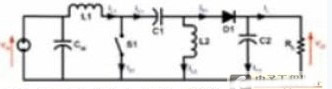
These inductors and coils are large in size and require more PCB space. This is even more unsuitable in applications where volume and board space must be maintained.
Start buck-boost converter
In automotive applications, the demand for buck-boost converters has grown dramatically over the past few years. This is especially beneficial for applications where voltage transients (eg, cold start) need to continue to “liveâ€.
The buck-boost converter is a typical DC-DC converter with an output voltage amplitude that is greater or less than the input voltage amplitude. It is a switch mode power supply with a similar circuit topology to the boost converter and buck converter. The output voltage can be adjusted depending on the duty cycle of the switching transistor.
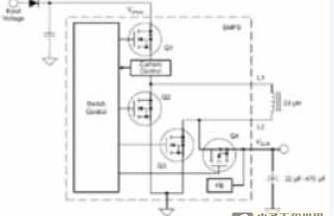
This topology consists of a buck power stage and its two power switches, which in turn are connected to a boost power stage and its two power switches via a power inductor. These switches can be controlled in three different modes of operation: buck-boost mode, buck mode, and boost mode. The special chip mode that runs is a function of the input-to-output voltage ratio and is also the control topology of the chip.
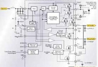
The TPIC74100-Q1 is a buck-boost switch mode regulator that operates under the power concept to ensure a stable output voltage with input voltage offset and specified load range.
The TPIC74100-Q1 has a complete voltage mode control switch that is also designed in a synchronized configuration for overall enhanced efficiency. With some external components (LC combination), the device regulates the output to 5V ± 3% to achieve a wide input voltage range that can be applied to many high input voltages. The device also provides a reset function for detection and indication when the 5V output rail exceeds the specified tolerance.
The TPIC74100-Q1 has a frequency modulation scheme that allows the system design to meet EMC requirements by spreading spectral noise over the frequency band rather than peaking at specific frequencies...
The 5Vg output is a switch 5V regulated output with internal current limit to prevent a "reset" assertion when driving a power line capacitive load. This function is controlled by the 5Vg_ENABLE terminal. If there is a ground short on this output (5Vg output), the output will self-protect by running in chop mode. However, in this fault condition, this will increase the output ripple voltage of VOUT.
Buck-boost conversion
This mode of operation automatically switches between buck and boost modes, depending on the input voltage (Vdriver) and the output load conditions.
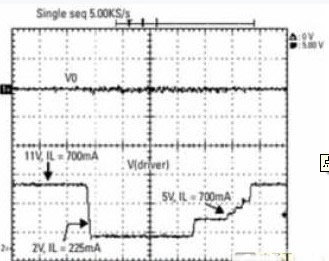
In normal operation mode, the system will be configured as a buck converter. However, during low input voltage pulses, the device automatically switches to boost mode operation to maintain a 5V voltage regulation. When the device is operating in boost mode and is in a 5.8V to 5V crossover window, the output regulation may contain a higher than normal ripple and maintain only a 3% tolerance. This ripple and tolerance depend on the load, and the higher the load condition, the higher the performance.
Low power operation
In some applications, such as the powertrain and instrument clusters, low power mode operation is required to minimize power consumption when the vehicle is "off." The TPIC74100-Q1 has an input LPM that will operate in PFM (Pulse Frequency Modulation) when it is turned on during light loads (typically less than 30mA). In most systems, many memory devices still require some power to retain data when the ignition is "off", typically requiring less than 100uA. To support this mode of operation, the total mode consumption should be less than 300uA. The TPIC74100-Q1 has a low power mode of 150uA (typ) quiescent current. The adjustment is done by a change in the switching frequency.
In PFM mode, the reduced amount of load current for the output load is not present. In this mode, the converter is less efficient, and the output voltage ripple will be slightly larger than in PWM mode due to the higher load current. Implement low-power mode functions for buck mode operation. In boost mode, the device will automatically enter PWM mode. By turning on the low power mode, the transition between buck and boost and the transition between PWM mode and PFM mode will occur simultaneously.
in conclusion
In many automotive applications, on-board transient voltage is a problem that will continue to challenge designers. The buck-boost converter will play a key role in many automotive power management system applications that need to be kept operating under these conditions, or when the battery voltage unexpectedly falls below the required output voltage level. The TPIC74100-Q1 automotive buck/boost converter simplifies design in automotive environments and enables design engineers to save on external component count and PCB space (with power switching and simultaneous operational integration). The TPIC74100-Q1 is available in a 20-pin PWP package with thermal pad and is specified over the -40°C to +125°C temperature range.
500mm*500mm Led Dance Floor and 1000mm*1000mm portable Dance Floor light are availble. Easy control with ISEELED control system. 1 pixel 1 LED Dance Floor , 16 pixels 1 wedding dance floor and 64 pixel 1 led disco dance floor are availble.It is IP65 waterproof led dance floor with good design of the housing. widely used in clubs, stages, wedding, disco and video art projects.
Photo show of LED Dance Floor:

LED Dance Floor
Led Dance Floor,Dance Floor,Led Disco Lights,Wedding Led Dance Floor
Shenzhen Iseeled Technology Co., Ltd. , https://www.iseeledlight.com