Currently, urban intelligent transportation systems have been widely used. Among them, the taxi center dispatching system has been fully utilized in some big cities. Management of taxi location and monitoring through global positioning system (GPS), public wireless transmission systems, geographic information systems (GIS), etc.
At present, taxi dispatching systems are generally divided into two categories: vehicle monitoring systems and vehicle navigation systems. With the development of GPS positioning technology and the emergence of GIS technology, the application research of navigation and positioning system based on GPS positioning technology has been carried out abroad. Currently, the French CARMINAT vehicle positioning and dispatching system is introduced. Taxi dispatching at home and abroad is a vehicle dispatching system suitable for the public, and the technology is also mature. However, for televocation services, it is now generally a manual telecommunications, and it cannot be well promoted; and the domestic and international mobile phone positioning is still in the research stage, and the mobile phone positioning technology is not very mature. This paper combines the existing taxi dispatching system with mobile phone positioning technology to provide a passenger call service solution.
1 system module design
The main technologies involved in the taxi dispatch center system are mobile terminal positioning technology, GIS, GPS, general packet radio service (GPRS), and C# and Sql Server2005.
1.1 overall system design
The taxi dispatch center is mainly composed of four parts, and its system framework is shown in Figure 1. (1) The dispatch center is the core part of the whole system, which consists of data service processor, database, GIS system [1] and so on. It is mainly responsible for the command, monitoring and provision of information services for taxis, the counting and processing of passenger information, and the exchange of data between passengers and passengers. (2) Taxi needs to provide geographical location information and taxi status to the center in real time, because most taxis have already installed GPS positioning systems and radio services [2]. In addition, taxis also need display and prompt modules. The passenger's location information can be obtained in real time. (3) The caller only needs to provide a car request to the center automatic or manual service desk, tell the center whether to wait in the place or give other boarding positions, and provide the center with the waiting time for the bus information. (4) The taxi dispatching center cooperates with the communication operator to request it to judge the location of the caller and return the location information to the center. 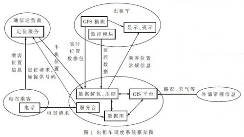
1.2 system detailed design
This article refers to the address: http://
The taxi information processing platform includes a microprocessor for data, control and management of each module, a GPRS receiving/transmitting module and a GPS receiving module [3]. Organize and collect taxi status and monitoring information. The control button realizes the simple control of the taxi driver to the system. The LCD display module displays the dispatching information sent by the center or the caller information. The sound signal mainly presents important information (such as alarm, security, etc.), and its framework is shown in Figure 2. . 
The processor is the core of the overall in-vehicle system, managing the data flow and control flow of the overall system. The design of the vehicle information processor selects the ATmega128 single-chip microcomputer of the VAR system, mainly completes the following functions: analyzing and intercepting the GPS signal, and writing to the temporary s storage unit; analyzing and integrating the signal received by the GPRS module, and displaying on the LCD Or write to the memory; package the GPS geographical location information, taxi status information, and vehicle camera photo information, and periodically send it through the GPRS module.
The GPS receiver module uses the Leadtek LR 9540 GPS module manufactured by LeadTek Corporation of Taiwan. The module uses the latest navigation chip based on SiRF star III, and receives data in 12 channels in parallel. It has a receiving sensitivity of -145 dBm and low power consumption. It provides standard RS232. The output is very suitable for use in various navigation and positioning equipment and moving targets such as cars and boats.
GPRS establishes a data channel between the vehicle terminal and the monitoring center at a transmission rate of up to 172 kb/s. After the NMEA-0183 standard data output by the vehicle GPS terminal is processed by the central control unit, it needs to be modulated by the GPRS Modem before it can be transmitted on the GPRS network [4].
The taxi driver allows switching control of the taxi system, but considering that the control of the lock will affect the safety of the driving, the taxi control module in the system should be as simple as possible and automatically handled as much as possible.
Usually cars have on-board power, but they can't directly supply power to the microcontroller, LCD, and modules. Voltage conversion is required. In general, the LM7805 and other voltage regulator chips can meet the power module requirements.
The central dispatching platform adopts a distributed architecture design, and divides the system into two service groups: the call-to-call information processing server group and the taxi dispatch server group.
The GIS platform uses MapInfo's MapX control [5] and is developed in C# language. The location information of the caller's passengers needs to be stored in the database in real time, and the taxi management also needs a database, so the platform uses the SQL Server 2005 database. The platform is mainly for the business process, services are handled for the needs of the callers, and the basic information of the taxis is managed, and the general information is sent to the dispatch center.
The taxi dispatch server runs in the client/server mode (C/S), and the dispatch client (mainly the GIS platform) sends a request to the server. After receiving the request, the server provides the corresponding service and returns the operation result to the client. Active request mode is adopted in the operation mode.
2 system software design
2.1 Overview of the dispatching center demonstration software
The dispatch center demonstration software is based on the development of C# language, Mapx map control and SQL Server 2005 database. Mainly achieve the following functions: (1) the basic operation of the map. (2) Taxi trajectory data simulation and passenger call information simulation. (3) Taxi information management and passenger information management. (4) Regular information transmission and track replay of taxis. (5) System settings, administrator management, etc.
2.2 Dispatching Center Passenger Information Processing Process
One of the most basic and important functions of the dispatch center demonstration software is the passenger's information processing. Find the nearest empty taxi by passenger location information and send the passenger information to the eligible taxi driver.
The passenger call information simulation interface will collect the passenger's location and identity information, and write it into the database for queueing. The dispatch center will select it. The result is shown in Figure 3. At this point, you can check on the map whether the coordinates of this passenger are within the taxi operating range. If the validity of the information disappears, the queue will be automatically discarded. 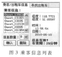
When the passenger information is selected and confirmed, the interface will display the information shown in Figure 4. At this time, the passenger information will also be displayed, and the effective time and location information will be integrated into a data packet. At this point, you will find the empty taxis with the right distance. The list box will list the taxis that meet the conditions. At this time, you can also set the taxis one by one, and select the most suitable one or more taxis for passenger information. send. So far, the processing of a passenger information has been completed. 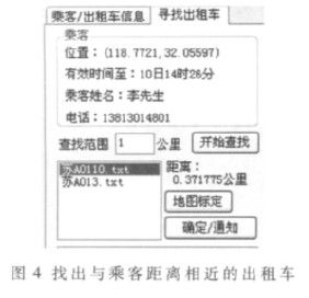
2.3 Database Design
In this demo software, the software library uses SQL Server 2005, which mainly includes taxi information management, passenger information management and administrator information. For taxi track information, the demonstration system uses text storage to store track data, such as:
$GPRMC,073943.48,A,3207.0664,N,11854.6808,E,0.00,231.40,020709,,,A*5D
The data is intercepted by "," as the mark to obtain information such as latitude and longitude, time, etc., which can save a lot of database space, is useful for data archiving, querying, etc., and is convenient for establishing a large number of taxi track data.
2.4 Simulation Demo
In the process of compiling the software, the form of software simulation is used, which has both the location information of the taxi and the location information of the passengers during the call, which ensures that the system has sufficient geographic data sources.
(1) Taxi GPS signal acquisition. The GPS signal periodically acquires geographical location information with a time interval of 1 s. For the convenience of data description, the spacing is set to be adjustable and automatically incremented. Double-click on a location of the map to generate an array and then write the Notepad file to generate location information. Figure 5 shows the flow chart of taxi GPS signal acquisition simulation. 
(2) Passenger signal simulation acquisition. The passenger clicks on the point on the map and calibrates it. After confirming, it begins to fill in the notification and fills in the information valid time. A screenshot of the passenger information simulation interface is shown in Figure 6. 
This paper takes the development of taxi dispatching system and transportation vehicle monitoring and dispatching system with the call service and taxi dispatch as the background. It analyzes the composition and working principle of taxi dispatch control system, and studies GPS, mobile phone positioning and GPRS. And the application of technologies such as GIS in this system. The taxi dispatch center demonstration software was developed using C# language, MapX control and SQL Server 2005 database. Finally, through the simulation of taxi GPS and passenger information to demonstrate the data processing process of the entire system dispatch center, the personal positioning technology is applied to the taxi call service, which provides the taxi call service that is not convenient at this stage. A solution.
This Dc Source System output current is up to 324A max by connecting the internal single unit Rack Mount Dc Power Supply in parallel. Output voltage is up to 750VDC max (recommend not to exceed 800V) by connecting the internal single unit in series.
Some features of these Adjustable Dc Power Supply as below:
- With accurate voltage and current measurement capability.
- Coded Knob, multifunctional keyboard.
- Standard RS232/RS485/USB/LAN communication interfaces, GPIB is optional.
- Remote sensing line voltage drop compensation.
- Equips with LIST waveform editing function.
- Use the Standard Commands for Programmable Instrumentation(SCPI) communication protocol.
- Have obtained CE certification.
75V Dc Source System,Ac Dc Electronics Power Supply,Dc Power System,Stable Dc Voltage Source
APM Technologies (Dongguan) Co., Ltd , https://www.apmpowersupply.com