EMI radiation generated during dimming and response
The EMI radiation of the SW pin output signal is a problem that mobile phone designers pay more attention to, but people often find that even if it has taken a lot of effort to reduce the EMI radiation of the SW pin output signal, the EMI problem still exists. The output voltage VOUT of the inductor-boosting backlight driver chip during PWM dimming may produce large output ripple. This is also an EMI source, but it is easily overlooked by cell phone designers.
Figure 3 shows the waveforms of the enable pin (EN) and the output VOUT of an inductor-boosted backlight driver using a normal PWM dimming mode during PWM dimming. As can be seen from Figure 3, when dimming with a 10KHz 50% duty cycle PWM signal, the ripple on the output voltage VOUT is as high as 4V. And we found that the lower the dimming frequency, the larger the output voltage ripple. In the PCB design, the output VOUT needs to be connected from the backlight driver module to the anode of the backlight LED of the screen, and the trace will be longer, so the output ripple of the VOUT trace is also a serious EMI radiation source!

Figure 3: Output VOUT ripple (10KHz, 50% duty cycle) when an inductive step-up backlight is driven by PWM dimming.
Excessive ripple amplitude on the output voltage can also produce harsh squeaks on the output capacitor. This is caused by the vibration generated by the piezoelectric effect of the output MLCC capacitor. A general whistling sound can be heard when the ripple amplitude exceeds 0.5V. Increasing the dimming frequency is a solution, but increasing the dimming frequency affects the dimming linearity of the PWM dimming, and even disables the dimming function, and does not fundamentally solve the problem.
Shanghai Aiwei's Inductive Boosting Backlight Driver AW9920STR/DNR uses an innovative PWM to constant current dimming method. PWM to constant current dimming receives a normal PWM dimming signal, which is converted by an internal circuit to finally output a constant output current. The magnitude of the output current is proportional to the duty cycle of the PWM dimming. The output current is constant and the ripple on the output voltage is very small. Figure 4 shows the AW9920's test results under the same conditions, while the AW9920's output voltage ripple does not exceed 100mV. The problem of EMI radiation and capacitor howling on the output VOUT is perfectly solved! And the AW9920 supports a higher dimming frequency. The higher the dimming frequency, the better the EMI performance and the capacitance howling problem are improved, and the dimming linearity is not affected.
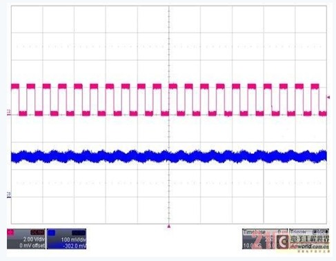
Figure 4: Output VOUT ripple (10KHz, 50% duty cycle) during AW9920 PWM dimming.
The use of variable slope drive technology and PWM to constant current dimming technology has made Shanghai Aiwei's second-generation series backlight drive EMI performance significantly improved. This design requirement for the PCB is greatly reduced, and the whistling of the output capacitor is also eliminated. However, EMI radiation is a very complicated and difficult to perceive problem. In the PCB design, the mobile phone designer should pay special attention to the fact that the connection to the SW pin is as short as possible and the area is as small as possible to reduce the EMI radiation on the SW trace. The inductor should be shielded as much as possible; the bypass capacitor of input VIN and output VOUT should be as close as possible to the corresponding pin of the chip; the trace of the power supply through the chip to ground should be routed according to the current trace to minimize parasitic resistance and parasitic inductance. The backlight driver module power supply and other module power supply lines should be connected by stars as much as possible; the ground wire should be grounded as much as possible, and separated from other modules that are susceptible to interference; the backlight drive module is recommended to be shielded with a shield. May reduce EMI emissions.
Edit: Nizi
Copper Led Lights Features:
High brightness, low power consumption
Outdoor and indoor decoration light
Made of high quality material, durable for daily use
Very low heat generating, besides saving light power
Energy-saving and environmentally friendly.
Long lifespan: more than 100000 hours.
Safe and environment-friendly, no radiation or pollution elements.
Light up your holiday party with the flashing string lights
Bright fairy lights to decorate your Christmas, wedding, party, festival, etc.
The lamp should be kept away from dampness, rain or mist
Copper Led Lights,Copper Wire Lights,Copper Led Lights,Copper Wire Led Lights
XINGYONG XMAS OPTICAL (DONGGUAN ) CO., LTD , https://www.xingyongled.com