After repeated trials, the author has produced a reliable electric bicycle quick charger, the circuit is shown in the drawing.
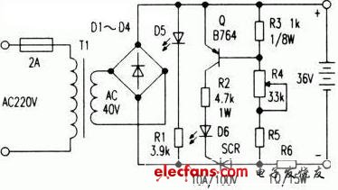
Self-made electric bicycle fast charger schematic
First, the circuit features
1. After the output voltage is set (for example, 36V), if the battery plate is disconnected and disconnected, causing a certain battery to fail, or a short circuit occurs, the voltage at the battery terminal is reduced or zero, and the charger will have no output current.
2. If the voltage of the bottle is deviated from the set voltage, if the set voltage is 36V, the battery is incorrectly connected to 24V, 12V, 6V, etc., the charger also has no output current. If it is set to 24V, it is connected to 36V battery, because the charger output voltage It is lower than the battery voltage and therefore cannot be charged to the battery.
3. If the two output terminals of the charger are short-circuited, the trigger circuit of the thyristor SCR in the charger cannot work, so the thyristor is not turned on and the output current is zero.
4. If the positive and negative poles of the battery are reversed during use, the thyristor trigger circuit is reversed, no trigger signal, the thyristor is not conducting, and the output current is zero.
5. Pulse charging is used to extend battery life. Since the low-voltage alternating current is pulsating DC after full-wave rectification, the thyristor is turned on only when its peak voltage is greater than the battery voltage, and when the pulsating DC voltage is in the valley region, the thyristor is turned off and stops to the battery. Charging, and therefore flowing through the battery is pulsating direct current.
6. Fast charging, full of self-stop. Since the voltage at both ends of the battery is low at the beginning of charging, the charging current is large. When the battery is about to be sufficient (the voltage at the 36V battery can reach 44V), as the charging voltage gets closer to the peak value of the pulsating DC output voltage, the charging current will become smaller and smaller, and it will automatically become trickle charge. When the voltage across the battery is charged to the peak value of the rectified output, the charging process stops. After testing, the three-section electric vehicle battery 36V (12V/12Ah three-section series) can be fully charged with the charger in just a few hours.
7. The circuit is simple, easy to manufacture, and requires little maintenance or repair.
Second, the circuit principle
The AC220V mains is stepped down by the transformer T1 and is supplied to the charging circuit after full-wave rectification by D1-D4. After the output terminal is connected to the set bottle by the correct polarity, if the peak value of each half of the rectified output ripple voltage exceeds the output voltage of the battery, the thyristor SCR is triggered to conduct by the collector current of Q. The battery is charged via a thyristor. When the pulsation voltage is close to the battery voltage, the thyristor is turned off and charging stops. Adjusting R4 can adjust the turn-on voltage of transistor Q. Generally, R4 can be adjusted from large to small to enable Q-switching to trigger thyristor (conduction). In the figure, the luminous tube D5 is used as a power source indication, and D6 is used as a charging indication.
Third, component selection
The power transformer can be controlled by BK200 type transformer, the output voltage is 36V, and the 4090 type 200V toroidal transformer can be used. The secondary voltage is 22Vx2 or 20V&TImes; the second gear is used in series. The 4090 type of the ring used by the author has a secondary voltage of 24Vx2, 12Vx2, and 0-6-23V. If the 24Vx2 block is connected in series (48V), the output voltage is too high and the charging current is too large (to 36V electric vehicle battery). When charging, the on-column ammeter measures the average charging current to be about 1.5-1.8A, which is the average value. At this time, the peak current can reach 5-7A or more. To reduce the transformer output voltage, the remaining 12V & TImes; 2 and O- The 6V two sets of coils are connected in series in the primary coil, so that the secondary output voltage is reduced to 40V at no load, and the full load (when the average charging current is 1.2A) is 36V, which is satisfactory. Because the 4090 toroidal transformer is priced at around 23 yuan. Can reduce production costs. Fans can also wind the transformer themselves.
In addition, the rectified full bridge D1-D4 in the circuit can be selected with a 8-10A square full bridge with a circular mounting hole in the middle, which can be mounted on the aluminum plate for heat dissipation. The thyristor can be sealed with a 1OA/100V gold unidirectional thyristor, and the same as the rectifier bridge nut is fixed on the same heat dissipation aluminum plate. The parameter of the triode Q is Vceo≥60V, IM=1A, and 2SB536, B564, B1008, B1015 or 2SA684, A720 and other tubes can be selected. R6 is used as a current limiting protection. If the secondary output voltage of the transformer is appropriate, the charging current (average value) does not exceed 1.5A, and the resistor can be omitted.
If the charger is used for battery charging of other voltages (such as 24V, 12V, etc.), the secondary output voltage of the transformer can be selected as 22V-26V, 12V-14V, etc., and the resistance of R2 and R5 should be appropriately reduced. The band switch can also be used to control the secondary AC voltage and resistance conversion, so that the charger has a larger range of use.
Fireproof safes (Fire-resistant safes) are designed to protect its contents from high temperatures and fire.
Details:
All of our products can pass CE and UL certifications;
Digital and mechanical variants available;
The effective time of resistance to damage is from 0.5-2 hours;
Door bolts are in a 4 way coverage
Financial Fireproof Safe,Lcd Display Fireproof Safe,Mechanical Safe ,Double Key Fireproof Safe
YONGFA INTELLIGENT TECHNOLOGY SECURITY CO., LTD. , http://www.yongfa-safe.com