Introduction
This article refers to the address: http://
Playing high-definition content (such as movies on Blu-ray Discs) requires a lot of processing power, which is not currently available in existing processors in current car infotainment systems. With the HDMI industry standard, automakers can integrate automotive HD movie playback capabilities more quickly and easily. Such systems can use automotive-grade Blu-ray drives that connect using E-type cables and connectors listed in the HDMI specification. Because the HDMI standard provides content protection for simultaneous audio (including multi-channel HD audio formats) and video transmission, there is no need to connect to the audio amplifier separately through other network or audio buses.
The Blu-ray player's playback function is just one application of HDMI in the automotive industry. More and more passengers and drivers are hoping to connect their mobile devices to car infotainment systems. In the near future, smartphones are expected to become entertainment centers, significantly reducing the processing requirements, complexity and cost of automotive infotainment systems. The design cycle of smartphones is much shorter than that of automotive infotainment systems. If smartphones become the hub of equipment, they can ensure that the latest consumer product developments can be quickly applied to automotive infotainment systems. HDMI delivers high quality, uncompressed feeds, making it ideal for connecting mobile devices to automotive infotainment systems. For the automotive industry, HDMI cables have low noise coupling and are not susceptible to other devices in the car.
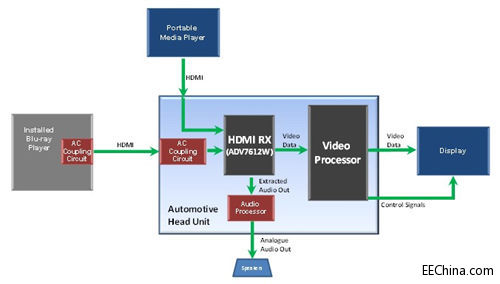
Figure 1: HDMI application in automotive design
Figure 1 shows an example of an HDMI application in a car design. The audio host (the main controller of the car infotainment system) has two HDMI inputs, one audio output, and one display video output. The HDMI receiver (Rx) decodes the video from the two HDMI inputs and extracts the audio. The audio is converted to an analog signal and connected to the speaker. The first HDMI input is connected to the installed Blu-ray player, which may be located in the trunk of the car. The second HDMI input provides connectivity to portable media devices equipped with HDMI, including smartphones, tablets, laptops, digital cameras and camcorders.
The HDMI interface is commonly used in consumer electronics, but how do you integrate it into automotive applications?
Although the HDMI interface is currently widely used in various home entertainment devices, automotive applications pose new challenges to the design using the HDMI interface. Automotive applications may include open systems or closed systems. Open systems allow for the connection of consumer devices such as smartphones or tablets. The closed system allows the interconnection of dedicated modules within the car entertainment system.
The closed system can be AC ​​coupled to provide short circuit (STB) and short to ground (STG) protection. Although this is not stated in the current HDMI specification, it provides a clever solution to common automotive application problems. If a fault occurs in the HDMI cable, a battery short or a short to ground occurs, the HDMI receiver and transmitter IC should not be damaged. The signal levels used in the HDMI interface are 3.3V and 5V, so shorting the car battery's positive terminal (12V) will usually damage the HDMI receiver and transmitter. If the HDMI interface is ac-coupled, the common-mode voltage between HDMI Rx and Tx will not damage the IC. In addition, an overvoltage protection circuit is required to protect the HDMI DDC lines because these lines cannot be AC ​​coupled. Figure 2 shows an example of how to implement a high level for STB and STG protection. The HDMI Tx and HDMI Rx AC-coupled circuits are designed for use in pairs.
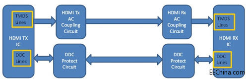
Figure 2: HDMI STB and STG Protection CCT Block Diagram
PCB design considerations
When adding STB protection circuits to HDMI TMDS lines, one of the big challenges we face is that it does not affect line performance or its matching impedance. To meet compatibility requirements, it is recommended to have the STB protection circuit as close as possible to the HDMI TMDS trace. This minimizes the length of the branch lines outside the trace and reduces the likelihood of reflections due to the branch lines.
How to implement AC coupling on HDMI TX?
Figure 3 shows a circuit that can be used to implement AC coupling on an HDMI Tx TMDS line. The ac coupling capacitor provides STB and STG isolation and should be considered a short circuit at the TMDS frequency. Must be able to withstand 18V DC voltage. Since the output of a car battery is typically 12V and the alternator output is about 14.5V, the STB test typically uses 18V to provide some safety margin.
The HDMI Tx switches the current source and requires a pull-up resistor for 3.3V. This shows the effect of a 100 Ω pullup resistor. Each line of the TMDS line differential pair must have an AC impedance of 50 Ω. This impedance is not shown here, but there is a second 50Ω series internal pull-up resistor on the downstream HDMI Rx. Connect a 100Ω pull-up resistor in parallel with two 50Ω resistors (in series with each other) for a total impedance of 50Ω.
The RCLAMP0524PA TVS (Transient Voltage Suppressor) device provides ESD protection. The inter-pin capacitance of the RCLAMP0524PA is only 0.3pF. This feature allows it to be used on circuits operating at frequencies above 3 GHz without signal degradation. It provides ESD protection for +/-15Kv air gap discharge and +/-8Kv contact discharge.
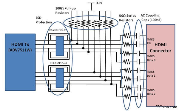
Figure 3: HDMI TX AC coupling on the TMDS line
HDMI TX AC coupling test
The circuit shown in Figure 3 was built and tested as follows: To verify the battery short circuit protection circuit, we shorted each TMDS line to an 18V battery and then functionally tested the HDMI Tx to ensure it was not damaged. The circuit has been tested to meet HDMI compatibility specifications at 27MHz, 74MHz, 148MHz and 165MHz. The only problem is in the low level output voltage (VL) test. However, the ADV7612 in the HDMI Rx AC-coupled circuit can withstand higher VL levels. This circuit has proven to work well at operating frequencies well above the 74MHz frequency of the HDMI E-type automotive connector.
How to implement AC coupling on HDMI RX?
In the circuit in Figure 4, the HDMI RX is AC coupled to handle STB and STG fault conditions. The AC-coupling capacitor blocks the common-mode voltage and protects the HDMI Rx from damage under STB and STG conditions. The upstream HDMI Tx must be AC ​​coupled for this circuit to work properly. If the HDMI Tx is DC coupled, it may not be able to detect the correct termination of the 100Ω resistor for each differential pair. The RCLAMP0524 device provides the necessary ESD protection. The 2KΩ pull-up resistor is used as a leakage resistor and the correct resistor value must be chosen to handle the increased current under STB and STG conditions. For example, under STB conditions:
P= (V2)/R= 182/2000= 0.162 watts
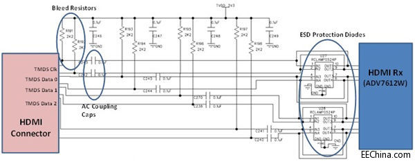
Figure 4: HDMI RX TMDS AC Coupling Circuit
HDMI Rx AC coupling test
This is the circuit of choice for automotive applications; the only circuit between the HDMI Rx and Tx AC coupling capacitors is the leakage resistor. This circuit has been verified to be unaffected by battery shorts and ground shorts. It also passes the HDMI TMDS compatibility test up to 165MHz, which is also the upper limit of the ADV7511W upstream transmitter. Figure 5 shows the differential impedance test results for Data Channel 1. The maximum differential impedance allowed is 115Ω and the minimum differential impedance is 85Ω.
Yuhai company develop and produce of various tube/cylinder sizes, bearing variety of electrode and metallisation configurations. The tubes is fabricated from various published and additional custom in-house Piezoelectric Material formulations for applications such as high power, sensitivity, stability needs.
Features
- · Choice of metallisation (Silver, Nickel, Gold and others on request)
- · Evaporated and chemically deposited metallisation's available
- · Thickness/Radial frequency tuning available on request
- · Wrap around electrode configuration
- · Wide choice of PZT formulations
aApplications include
- · Hydrophones
- · Fibre optic stretcher
- · Augmented reality
- · Torpedo decoys
- · Accelerometers
- · Pressure sensors
- · Print head transducers
- · Oil and gas exploration
- · Scientific equipment
Tubes
Height:
1-100mm
OD:
6-180mm
ID:
5-150mm
Wall: 0.5-15mm
PZT Piezoelectric Cylinders/Tubes
Piezo Tube,Piezoelectric Tube,Piezo Electric Tube,Piezo Ceramic Tubes
Zibo Yuhai Electronic Ceramic Co., Ltd. , https://www.yhpiezo.com