"Machine Vision" has many uses. With the rapid development of optoelectronics, automation and computer image processing technology since the 1990s, machine vision has become more and more widely used in many industrial sectors including automobile manufacturing. As a novel and practical sensing technology, the image detection unit has been commercialized in recent years. Some well-known manufacturers, such as Panasonic Corporation of Japan and Siemens of Germany, have launched a series of products with complete specifications, including light sources. , camera, processor, etc., have created favorable conditions for the promotion and application of image detection technology. At the same time, the relevant standards issued not only regulate the production, but also provide the basis for the user to select the appropriate detection unit in different situations to make the system design faster and better.
This article refers to the address: http://
In contrast, the domestic industry is still in its infancy in this regard. Even in the rapidly developing automobile manufacturing industry in the past 20 years, the application of machine vision is quite limited. However, the application prospects of this new technology can be clearly seen through the following application examples.
Application in precision measurement

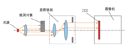
Figure 1 Schematic diagram of the displacement detection system
Precision measurement is an important application field of machine vision. The principle of measuring the object to be measured is shown in Figure 1. The detection system is mainly composed of an optical system, a CCD camera, and a computer processing system (not shown). The parallel beam emitted by the light source is irradiated onto the detection portion of the object to be measured, and the edge contour is formed by the microscopic optical mirror on the surface of the CCD image of the camera, and the image is processed by the computer to obtain the position of the edge contour of the measured object. . If the measured object is displaced and its edge contour position is measured again, the difference between the two positions is the displacement amount. Obviously, if the two parallel edge contours of the measured object can be in the same image, the difference between the two positions is the corresponding size.
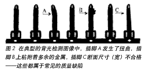
The above system is very suitable for on-line detection of workpieces in mass production situations, especially when the measured object is small in size and simple in shape, it can show its superiority. Electronic connectors, including connectors in automotive electronics, are typical examples of high productivity and dimensional accuracy of the finished product, with the former reaching hundreds of parts per minute, while the latter are mostly on the order of 0.01 mm. When measuring with the system shown in Figure 1, the image formed by the part (pin) has a clear silhouette effect due to the strong contrast with its bright background. Such an ideal image creates conditions for accurately measuring the size and contour (shape) characteristics of the object to be inspected. Figure 2 shows a typical backlit image of a portion of the stamped shaped prong as the metal conveyor passes through the inspection station.

It should be pointed out that although the edge detection of the part image is adopted, there are still differences in the specific methods depending on the workpiece. For example, three (L1, L2, L3) or multiple detection lines can be set on the image of the part (pin) shown in Fig. 2, and the edge information of the part is detected by a simple threshold method or a single double peak method. Since the three detection lines are kept perpendicular to each other, the position (X, Y) and the rotation angle (?) of the pins with respect to the image plane can be determined by the edge detection points of the simultaneous 3 lines (or multiple lines). The position information (edge ​​coordinates and starting corners) of these target parts will be transmitted to the computer processing system for evaluation.
Another example of image detection technology for precision measurement is the application of tool presetting measurements. The traditional method of detection is the combination of optical projection and raster digital display. The former is used for aiming and positioning, and the latter is used for measurement and reading. The whole process requires more manual participation, and the requirements of the operators are high and the efficiency is low. The novel tool pre-adjustment measuring instrument that was born a few years ago combines machine vision, grating technology, computer hardware and software, and automatic control technology to make a fundamental change in the traditional working mode, regardless of measurement accuracy, ease of operation and work efficiency. There has been a tremendous improvement. The main reason is to replace the traditional optical projection with machine vision, thus completely changing the original working mode.
In this novel instrument, a linear grating and a circular grating are respectively mounted in the Z-axis, the X-axis, and the C (rotary) axis of the moving guide, and the tool to be tested is mounted along the center line of the turntable (ie, the C-axis). Machine vision sensors are located on either side of the fork bracket, that is, across the centerline of the turntable. One end of the bracket is placed with a light source, and the other end is a camera, and the image of the tool to be tested is read by the camera.
Detection of surface defects of workpieces
Detection of surface defects In the mass production of automobiles, motorcycles, internal combustion engines and other industries, artificial visual methods have been used to date. Such a method is not only inefficient, labor intensive, but also difficult to accurately perform the quantitative assessment requirements specified in the process standards, thereby affecting the effective monitoring of product quality.
.
Taking the joint surface explosion of the connecting rod as an example, the specific requirements of the evaluation standard are: the breaking area is less than 3 mm2; the linear length in either direction of the breaking is less than 2.5 mm. As long as any of the above conditions are met, the judgment is rejected and rejected.
It must be pointed out that, unlike the transmission method (also called "backlight" mode) used in the machine vision system in the above precision measurement, the reflection mode shown in Fig. 3 is required for surface defect detection.
The system illuminates the broken area of ​​the workpiece to be inspected by a square frame type LED diffuse reflection light source, and the light is irradiated onto the surface of the object, and is reflected on the photoelectric coupling CCD element in the camera, which is converted into a corresponding electric quantity signal; the image processing system The obtained image is analyzed and calculated according to the power signal, and finally the required data is obtained. After the system binarizes the obtained image, the binary image is used as an object for further calculation and analysis.
In actual use, the system uses a comparison method for the binarization threshold of the gray scale and the setting of the light source, that is, using the known sample as a reference for calibration. Measure known reference objects
The value is divided by the pixel value corresponding to the reference object to obtain a corresponding scale value between the pixel and the actual value. By adjusting the brightness of the light source and the binarization threshold of the system, the binarization threshold of the gray level is optimized to ensure that the system has a relatively high resolution on the object boundary, that is, the optimized binarization threshold and the light source can make the boundary The change produces as large a change in pixel value as possible.
According to the characteristics of the object to be tested (piece shape, measured part) and requirements, refer to the relevant standards of the vision system product, and according to the completed design, the appropriate image detection unit (device) can be conveniently selected to form the corresponding detection. system. Taking the link joint surface explosion as an example, the detection requirements of the system are as shown in Fig. 4, that is, the mutual detection is 15 respectively. At the angle of the ABC three (on the side of the link), the maximum value of the three test results is used as the actual value of the break, and the result is output. Figure 5 is a schematic diagram of the system composition, wherein:
1. The CD camera is used to capture the broken image and convert it into a digital image signal;
2. LED light source is used to provide stable and uniform illumination to ensure image quality;
3. The purpose of the image processing unit is to process and analyze the collected image according to needs, and simultaneously transmit the analysis result and the state information of the image system to the PLC through the RS232 interface to provide signal output and data exchange;
4. PLC controls the execution of each function of the whole detection system, and also checks and judges the data transmitted by the image processing unit;
5. As a human-computer interaction interface, the monitor displays the status of the image processing system and the results of the data analysis.
Application in the automotive industry
Although the detection principle of the machine vision system for image recognition is similar to the above surface defect detection, its function and purpose are completely different. In contrast, even in the domestic automotive manufacturing industry, there are more applications than the first two areas.
.
Modern industry has increasingly adopted end-products and even semi-finished products (components) with one-dimensional and two-dimensional bar codes for identification. Under the conditions of mass production, how to identify and judge them? If relying on artificial visual inspection, not only labor intensity, but also inevitable mistakes. On the other hand, in the production line, especially the operation of those assembly processes, in order to correctly complete the specified requirements, it is often necessary to interpret one-dimensional, two-dimensional bar codes or to identify certain printed fonts; in addition, in many cases, for parts The attitude and position (direction) must also be identified, especially when using the optional assembly method. Electronic tags are also a new technology developed in recent years. They use machine vision recognition technology to wirelessly write tags or read out various quality information related to the engine through the reader. An electronic tag is mounted on the conveyor (tray) of some engine production lines, and a reader/writer is placed in each processing or assembly station. The reader is connected to a PLC or computer.
1. Assembly of the piston in the cylinder
When the image recognition technology is used in the “piston-cylinder assembly processâ€, the main steps include: judging the cylinder in place and preparing for the test; detecting the upper edge of the cylinder (the sign in the exact position), if the feature is not found, That is to send an alarm signal; establish a coordinate system in the detection system; identify such three items: the presence or absence of the piston, the correct position of the piston (exactly
Is the "orientation"), the logo and characters on the top surface of the piston - used to indicate the model, the type of assembly selected, and other relevant meanings.
The whole process of detection and identification is as follows: the engine is turned over and loaded into the piston, and the conveying system moves the engine to the inspection station with the pallet; when the engine is about to reach the inspection station, the electronic tag reader confirms its "identity", and then Signal to the PLC; when the engine reaches the detection station, the proximity switch triggers, the PLC issues a work command to the machine vision system; if the piston is assembled correctly in the cylinder, the vision system sends a letter to the PLC, then writes the electronic tag, the engine Continue to flow to the next station. If the piston is assembled incorrectly, the vision system prompts the PLC and alerts through the HMI. The display will indicate which cylinder has the wrong assembly and what is wrong. After confirming the result of the test, the operator writes the result to the electronic tag by issuing a command from the human-machine interface PLC, and directly transports the engine to the repair area for repair. The entire inspection process is completed automatically, only by manual intervention in the event of assembly errors and alarms.
2. Assembly of the main bearing cap on the cylinder block
In the cylinder production line of a four-cylinder engine, the assembly of the main bearing cap on the cylinder is another typical example. The front end portions of the five main bearing caps are different in steps and are different. Installed in the specified order and orientation by the digital identification on each part. Due to the mixed parts and large quantities, misassembly often occurs, resulting in waste in the next process.
To this end, a testing station is set up between the tightening assembly station and the turning station of the production line, and the correctness of the assembly result is judged by automatic identification. If all is correct, the cylinder will continue to flow to the next station, otherwise the alarm will be given to the PLC to stop the production line and repair the defective cylinder. In order to adapt to the assembly beat of 1 piece/min, it is detected during the movement of the cylinder, and two photoelectric vision sensors are arranged on the upper side and the side of the production line, respectively. The former is a part positioning sensor for automatically and accurately triggering the sampling, and the latter is used to dynamically identify the surface geometry of the five main bearing caps. Based on the pre-inserted main bearing cap characteristic parameters and the collected sensor output signals, it is possible to determine whether the error is set and the specific error position is indicated.
The whole detection and identification process is as follows: after the completion of the tightening process of the main bearing cap, the cylinder body moves along the roller table to the inspection station, and the restraining action of the guide rails on both sides ensures the automatic alignment of the parts. When entering the inspection station, the positioning sensor first detects the edge of the first main bearing cap, and then the geometry of the front end portion is recognized by another sensor, which is sampled and processed by the controller; then the cylinder continues to move forward, for the second to The fifth main bearing cap is detected and identified. By comparing with the preset value, it is possible to judge whether there is a misplaced part. Each probe has a count and display, and the entire inspection process is completed in the cylinder transport movement without additional test time.
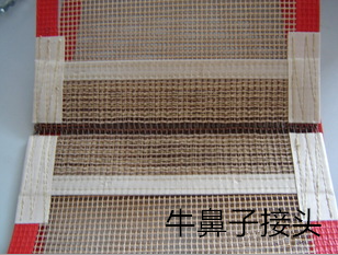
Bull nose is a common connecting way of Conveyor Belt, which is named for its shape.
The joint mesh is made of Kevlar coated with Teflon dispersion, whose technical is similar to PTFE open Mesh Conveyor Belt.
Compared to PTFE fabric conveyor belt, bull nose is much more suitable for open mesh conveyor belt, and easy to install and to repairing. In addition, the price is more competitive than alligator joint. Besides, the conveyor belt with bull nose can apply in micro wave situation.

PTFE Conveyor Belts With Bullnose
Industrial Conveyor Belts,Conveyor Belt With Bullnose,Mesh Conveyor Belt With Bullnose,PTFE Conveyor Belts With Bullnose
TAIZHOU YAXING PLASTIC INDUSTRY CO., LTD , https://www.yaxingptfe.com