Abstract: This paper proposes and implements the use of wireless transmission in vehicle travel records. The wireless module is added to the car tachograph and a wireless transmission protocol is designed to quickly detect data in the recorder, such as timeout, overspeed, and the like. The test results show that the method can move, obtain information remotely, quickly and accurately, and has good cost performance and promotion value.
Keywords: wireless car drive recorder; wireless detector; ARM processor; wireless module
0 Introduction With the rapid development of road traffic, the road traffic accident rate is constantly rising. Overtime driving and speeding have become the main causes of traffic accidents. A car tachograph (hereinafter referred to as a recorder) is a digital electronic recording device that records, stores, and transmits data of a vehicle's traveling speed, time, mileage, and other state information about the vehicle's travel. The use of the vehicle tachograph has an important role in curbing the traffic violations such as fatigue driving, vehicle overspeed, restricting the driver's bad behavior, ensuring the driving safety of the vehicle, and analyzing and identifying road traffic accidents. However, in the actual use of the existing car recorder, the traffic police department often cannot obtain information such as timeout and overspeed in real time, and thus cannot effectively stop overtime speeding. Therefore, research and development of wireless vehicle driving recorders and wireless detectors (hereinafter referred to as detectors) are used to quickly obtain timeout overspeed information in the timeout overspeed recorder. The wireless detector adopts a handheld terminal design scheme, which can detect and communicate with the surrounding wireless vehicle driving recorder, and can realize the wireless detector to read the timeout and overspeed information in the vehicle driving recorder.
1 wireless data transmission
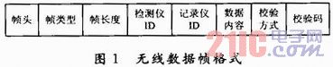
1.1 Wireless data frame The wireless data frame format retains the data frame header specified in the national standard of the vehicle tachograph, and six data frames are added on the basis of the data frame used only by the wireless data transmission unit. The basic format is as follows. Figure 1 shows. The newly added data frames are: data acquisition, data response, timeout data request, timeout data response, overspeed data request, and overspeed data response, respectively, for detecting the acquisition of detailed information in the recorder and the recorder.
This article refers to the address: http://
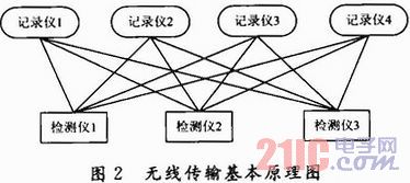
1.2 Wireless transmission scheme design The basic principle of wireless transmission in this paper is shown in Figure 2. It adopts multi-point to multi-point data transmission model and adopts call data transmission. When the detector i (i = 1, 2, 3) issues a data acquisition signal, if the recorder j (j = 1, 2, 3, 4) successfully receives the signal, then t (t does a random number within 500 ms) ) A data response frame is returned to the wireless detector during the time. The detector is able to capture the timeout and overspeed information flags in the surrounding recorder. When the detector i needs to check the details of the timeout or overspeed in the recorder j, it sends a timeout or overspeed data request message again, and waits for the timeout or overspeed data response frame of the recorder j to obtain detailed timeout or overspeed information.
During data transmission, if the detector sends a request data frame and does not receive any response data, it will resend the current data frame until the maximum number of times N (N=3). The detector and the recorder check whether the corresponding ID in the received data frame is consistent with itself, and if not, discard the processing of the data frame.
2 system hardware design
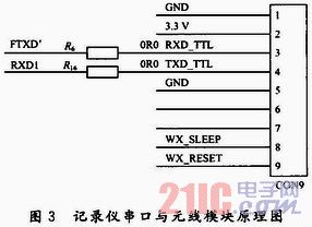
2.1 Recorder wireless interface circuit design Based on MVR-E type recorder hardware, this product uses LPC2214 ARM7 processor as the processing core to realize the function of the car recorder. On this basis, add wireless transmission. unit. The wireless module adopts SWRF-1101. This wireless module has its own wireless collision detection mechanism. When the wireless module collides wirelessly in the air, it can automatically detect collisions and delay retransmission. SWRF-1101 is the data communication carrier between the detector and the recorder. The wireless codec is automatically completed by the wireless module. The wireless module uses a serial port to interact with the recorder, and its connection diagram is shown in Figure 3.
2.2 Detector hardware circuit design The system uses STM32F103VET6 microprocessor as the control core, STM32 series microprocessor belongs to 16-bit MCU, and STM32F103VET6 has the characteristics of reduced instruction set and low power consumption and high speed. 72 MHz. The STM32F103VET6 has 512 KB of FLASH and 64 KB of RAM for better communication protocol resolution. The system hardware block diagram is shown in Figure 4.
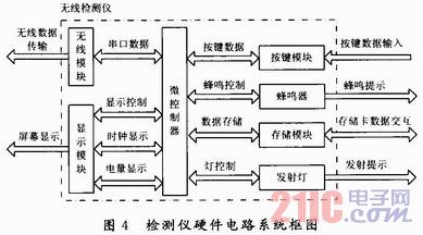
The system human-computer interaction unit consists of a waterproof button and a 2.8-hour color LCD screen. The buttons include an input control unit that combines, confirms, returns, flips up, and turns down to form a detector. The display adopts ADS7843 chip and is controlled by hard SPI interface. ADS7843 is a 4-wire resistive touch screen conversion interface chip produced by TI Company. It can realize touch input and color display. In this system, only color display is used.
The detector records the license plate recorded at the time of data collection and the timeout overspeed information of the corresponding recorder. The data collected from the recorder needs to be stored in the mobile storage device, and other information is stored in the power-off protection storage device. Therefore, the detector uses the ferroelectric FM24V02 chip to store the power-off protection data. The chip has a capacity of 256 Kb and can read 100 trillion times, which can store data stably and reliably. The detector uses the SDIO of the STM32F103VET6 itself to drive the SD card and store the mobile data that needs to be exported.
3 system software design
3.1 Recorder Software Design The MVR-E recorder is based on Keil3 and uses the C language to implement the recorder function. On this basis, the implementation of the wireless transmission scheme is added, and the basic flow chart is shown in FIG. 5.
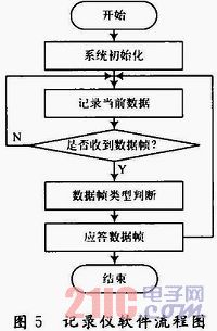
While recording the current driving data of the car, the recorder simultaneously monitors the data received by the wireless module. When the data frame is successfully received, the recorder temporarily returns the overspeed status and information to the corresponding data frame of the detector. The data frames that need to be acknowledged include: data acquisition, timeout data request, and overspeed data request. When answering the data collection message, it only needs to answer the timeout overspeed flag, and when responding to the timeout data and the overspeed data request, the specific violation data needs to be sent to the detector.
3.2 Detector software design Detector software system block diagram shown in Figure 6, divided into driver layer and application layer, the driver layer is mainly to achieve the drive of each hardware unit, the application layer to achieve the functional application of the entire system, its development environment is Keil4, using C language as the programming language.
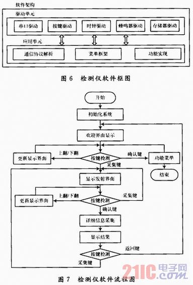
The application flow chart of the detector software is shown in Figure 7. The software flow is mainly implemented around the button detection, detecting that different buttons perform different functions according to the existing directory conditions. The system may press the capture button to implement the acquisition function under any interface.
The detector software realizes the ability to collect response information of up to 10 vehicles at the same time, and displays the received vehicle license plate number on the screen, and visually displays the timeout, overspeed and other signs through the color information. After pressing the confirmation button again, the details of the data are collected again. And it is visually displayed on the display, and the currently displayed content can be stored in the SD card for review.
4 Experimental results The wireless vehicle driving recorder and the wireless detector were measured and used on the Jinlong bus, which achieved good results. The results of use are shown in Figure 8. The figure shows the data read by two wireless car tachographs. One of the recorders tested the resulting image at the same time as another recorder with no timeout information after 2.1 hours of continuous driving. The timeout speeding will be indicated in red, the non-violation information will be indicated in green, and the lower left and lower right images will be the collection of detailed information of the two vehicles.
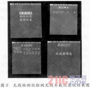
In the specified timeout driving time (for test convenience, 2 hours), the overspeed data during driving can be accurately recorded and can be wirelessly read by the detector software, and the tested wireless reading distance can reach 100 m. When the continuous driving time is 2 h, the detector can read the timeout information and display the start and end time on the screen.
5 Conclusions This paper proposes a novel data transmission design scheme for recorders. The vehicle driving recorder on the market cannot realize the fast uploading of illegal information on the spot, and the combination of wireless detector and wireless vehicle driving recorder solves the present problem. There is a problem of data upload lag in the vehicle driving recorder, which is very helpful for preventing traffic safety accidents and timely curbing traffic violations. The experimental results show that the product has the characteristics of mobile acquisition, fast acquisition of recorder information, and long effective distance collection, which has certain practical value and promotion value.
Corn Sheller,Hand Corn Sheller,Corn Sheller Machine,Hand Crank Corn Sheller
Hunan Furui Mechanical and Electrical Equipment Manufacturing Co., Ltd. , https://www.thresher.nl