In the 1980s, low-power small quartz metal halide lamps with precise dimensions achieved breakthroughs in both design and production. At the same time, with the acceleration of people's life and communication rhythm and the completion of highways, it is required to continuously improve the safety of night driving. Therefore, it is necessary to have a good headlight visual structure. Therefore, countries around the world have begun to use low-power bismuth metal halides. The lamp replaces the conventional tungsten halogen lamp as the light source for the car headlight. The requirement for instantaneous illumination of the headlights of the vehicle is met by charging the lamp with a high pressure helium gas of several atmospheres as the starting gas. At present, the high-intensity automotive headlamp electronic ballast system is one of the research hotspots, but the electronic ballast is complex in design, expensive, and bulky, and is only suitable for high-end automotive applications. Obviously, if the volume and cost can be reduced, the demand will increase a lot, so it has a good application prospect.
This article refers to the address: http://
This paper proposes an electronic ballast for analog headlights, which realizes the use of analog circuits to control the various control tasks of the headlights from start to stability, including constant power and ignition control.
Basic circuit structure
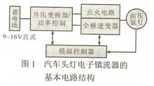
In order to meet the different requirements of the lamp in starting and steady state, the basic circuit structure of the electronic ballast for automobile headlights generally used includes the four-part function shown in FIG.
(1) DC/DC booster circuit Since the current power supply for automobiles is a 12V lead storage battery, and the steady state voltage of the lamp is about 85V, the battery voltage must be increased by the primary boost circuit.
(2) The high-voltage start-up circuit requires a high-voltage pulse to cause the lamp to break down and start discharging, so a high-voltage start-up circuit is required. The startup circuit can take a one- or two-stage boost to generate a high voltage pulse of at least 23 kV.
(3) DC/AC conversion circuit Since the output of the DC boost circuit is DC power, the inverter circuit must be used to convert the DC power into the AC square wave current required by the lamp. Inverter circuits generally use full-bridge inverters. The full bridge inverter circuit provides low frequency AC square wave current to the lamp to avoid the occurrence of acoustic resonance.
(4) Control and start-up circuit when the drive and protection circuit lamps are activated. After the lamp is lit, check for overvoltage and short circuit. The control circuit and the protection circuit are controlled by detecting the signal of the lamp voltage and the lamp current, so that the lamp can work stably.
Main circuit topology selection
In addition to meeting the normal working requirements of the lamp, the boost converter must also consider the no-load output voltage capability of the circuit. The level of the no-load output voltage determines the design of the ignior circuit and the takeover circuit.
(1) Boost circuits are the simplest among many circuit topologies. When the switch S operates at a large duty cycle, a high output voltage can be obtained. However, under such operating conditions, the output diode has a reverse recovery problem, and the voltage and current stress of the switch is high and the loss is large.
(2) For the forward converter, although the purpose of boosting can be achieved, the no-load output voltage capability is not as good as that of the flyback converter. The transformer of the forward converter does not need to store energy, so the size of the transformer core can be small, but in order to output a voltage of 400V, the number of turns of the secondary winding must be increased, thus requiring a large window area. Therefore, excessive secondary windings will cause an increase in copper loss of the transformer, which is disadvantageous for improving efficiency.
(3) Using the Flyback converter as the DC/DC stage topology, the switching stress of the DC/DC stage is reduced by adding the ignition winding method, and the circuit reliability is increased; if the digital control is used, the circuit can operate in a critical continuous state. More functions can be implemented, which reduces circuit cost.
.
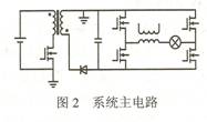
In addition, there are many main circuit topologies for automotive headlamp electronic ballasts that take into account these methods. The Flyback converter plus the low-frequency full-bridge inverter circuit shown in Figure 2 is generally used as the main circuit topology.
Control circuit design
The problem of starting the lamp is a hot spot at present, so there are many researches on its control method. Through the optimization of the control system, the dynamic response speed of the system is improved; the warm-up time of the lamp is shortened, the lamp can quickly enter the arc discharge; the electrode loss of the lamp is reduced; and the life of the lamp is prolonged.
1 using analog circuits to complete the control strategy
Figure 3 shows a low cost, simple and feasible analog control circuit designed. It is fully capable of providing the various control functions required during the various stages of the car's headlights from start-up to stabilization.
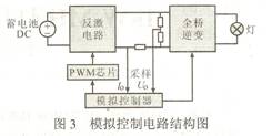
2 constant power control scheme
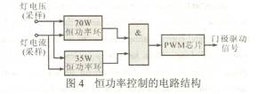
It can be seen from FIG. 3 that the overall load of the full-bridge inverter circuit only consumes the active power of the lamp, so the power consumed by the lamp can be approximated as the input power of the inverter. Therefore, by continuously sampling the output voltage Uo and the output current Io on the lamp loop, a parabolic approximation constant power control method is used, and an analog circuit is used to realize constant power control with a control accuracy of about ±5%. However, the headlights of the car are special. In order to meet the special requirement of reaching 80% of the rated light output within 4s, 70W of transient power is initially supplied to the lamp, and the headlight of the car is rated at 35W. Therefore, two constant power control loops are required in the design, and the switching between the two is realized by a gate circuit, and FIG. 4 shows the circuit structure of the constant power control.
3 ignition control scheme
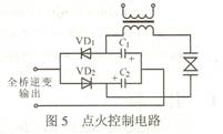
The ignition method uses pulse ignition, and the circuit uses a voltage doubler rectifier circuit. Figure 5 shows the ignition control circuit. The forward voltage of the full-bridge inverter output turns VD2 on first, and charges capacitor C2; the output negative voltage turns VD1 on and charges C1. When each capacitor is charged to 400V, the 800V gas discharge tube can be turned on to start discharging. Thus, when the transformer primary generates an 800V pulse, the secondary generates a high-voltage pulse of tens of thousands of volts, thereby avalanche the high-intensity gas discharge tube.
Experimental result
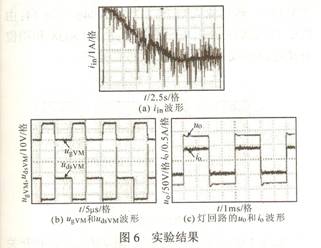
Experimental demonstrations were carried out on the basis of the above-mentioned principle analysis and implementation discussion. The experimental prototype is an electronic ballast with a rated power of 35W automotive headlamps. The boost circuit uses a flyback circuit and uses UC3843 as the PWM control chip. The main circuit parameters are: IRF540 selected for the MOSFET switch of the flyback circuit; MUR860 for the diode, Lp=7.8μH for the primary inductance of the transformer, and 1μF CBB capacitor with a withstand voltage of 630V for the output capacitor. Fig. 6b shows the experimental waveform of the driving voltage UgVM of the switching transistor and the voltage UdsVM across the drain and source of the switching transistor in the steady state of the flyback converter. It can be seen that UdsVM has a big spike, which is caused by the energy of leakage. Figure 6c shows the actual operating waveform of the voltage uo at both ends in steady state and the current io flowing through the lamp. As can be seen from the figure, the output power at both ends of the lamp will be nearly 35W, which is in good agreement with the theoretical design.
The basic circuit structure of the electronic ballast for analog control car headlights and the choice of circuit topology are studied. Through the production of the actual prototype, it is demonstrated that the analog circuit can be used to realize the complex control requirements of the car headlight from start to stability; it illustrates the rationality of the electronic control circuit design of the entire analog control car headlight.
Ultraviolet Lamp,Pls Uvc Light,Pls Uvc Bulb,Pls Uvc Tube
Changxing leboom lighting product CO.Ltd. , https://www.leboomuv.com