CATV Network Technical Paper
Abstract: This article comprehensively introduces the system components currently implemented in the Beijing cable TV network, especially the topology of the fiber optic coaxial cable hybrid network-hfc hospitality access network, and the implementation of two-way transmission.
Keywords: line television network, coaxial cable hybrid network, hfc, bidirectional transmission
l Phased development of cable TV system technology China's cable TV began in the 1970s. After more than 20 years of development, it has grown from scratch to small. Today, it has developed into an emerging industry in the field of radio and television in China. From the self-reliance, starting from scratch, to the introduction of foreign advanced equipment, China's cable technology has developed rapidly. From vhf frequency band, all-channel shared antenna system to 750mhz, 860mhz cable TV metropolitan area network system, from coaxial cable to optical cable, cable, mmds and other transmission technology mixed applications, from only transmitting analog signals to analog and digital signals Hybrid transmission, from one-way broadcast network to two-way interactive network. At the same time, the successful use of advanced data transmission equipment, digital transmission systems and computer technology in the cable TV system, the development of China's cable TV technology is increasingly approaching the international advanced level. Today, it has established its basic network status in the "three networks and one platform" of the national information structure framework. Cable TV is advanced in technology, has good social and economic benefits, and is a national infrastructure construction project.
In general, the development process of China's cable TV can be divided into three stages, namely: small shared antenna system, large shared antenna system and cable TV system.
1.1 The stage of the small shared antenna system (1975-1985)
1. Spontaneous growth
2. Self-financing of funds
3. Enterprise initiative
4. Decentralization of the system
5. Limitations of the program source
1.2 The stage of large-scale shared antenna system (1985-1995)
1.3 The stage of cable TV system (1996-present)
The development stage of the cable television system. Make full use of international advanced technology, adopt optical fiber, cable, mmds microwave and other transmission technologies according to local conditions, and build cable TV networks within the administrative regions of provinces, cities and counties. Currently. It is developing in the direction of large capacity, digitization, and bidirectional multi-function.
After several years of network practice, an a platform focused on transmitting radio and television programs and a b platform focused on transmitting data have achieved success. It not only guarantees thousands of households to watch high-quality radio and television programs, but also provides high-speed, large-capacity, low-cost, safe and reliable transmission means for data communication and transmission of various information.
At present, most of China's provinces and cities have opened optical cable trunks that use digital technology to achieve networking across the province and the city. At the same time, the national backbone network uses advanced digital transmission technology to provide a high-quality service platform for digital and data transmission services. China's cable television has entered the experimental stage of realizing digital and interactive high-speed multimedia information network.
2 Cable TV system performance indicators and related standards
2.1 Basic concepts
1. Cable televiTIon (catv): A television system that uses radio frequency cables, optical cables, multi-channel microwaves or a combination to transmit, distribute and exchange sound, image and data signals.
2. Pay-tv: Pay-tv: Adding and descrambling technology, users need to pay extra to watch TV programs.
3. Two-way cable TV: two-way cable TV system with uplink and downlink transmission
4. Front end: In the cable TV system, it is used to process various wireless signals received by the antenna and self-run program signals.
5. Sub-head hub headend: System auxiliary front end, usually set in the center of the service area. It transmits analog and digital TV signals downwards, and simultaneously receives signals from all users in the service area for uplink transmission.
6. Trunk system trunk feeder system: In the cable television broadcasting system, it is used for the transmission of signal links between various front ends or between the front end and each distribution point or each optical node.
7. Optical link opTIcal link: A link that uses optical fiber communication technology to transmit sound, image and data signals. Generally composed of optical transmitter (electrical / optical converter), optical fiber, optical receiver (optical / electrical converter) and other necessary optical devices (such as optical amplifier, optical connector, optical splitter and optical attenuator, etc.) .
8. Optical fiber coaxial cable hybrid network (hfqhybrid fibercoaxial access network with optical fiber as the trunk and coaxial cable as the distribution network).
9. Optical node fiber node: It is a node that completes the conversion of light, electricity or electricity and light in the hfc network. It is connected to the front end (sub-front end) with optical fiber and connected to the distribution network with coaxial cable.
10. Downstream transmiwssion path: a part of the hfc network whose signal is distributed from the front end or any other central node to the user's network part in the downstream direction.
11. Upstream transmission path: A part of the hfc network whose signal goes from the user connected to the network to the front end or any other central node in the upstream direction.
12. System outlet: An interface device that connects the subscriber line and the incoming line of the receiver.
13. Two-way subscrider port: a duplex access port that can transmit signals downwards and upwards in the user room.
2.2 Performance definition
1. Image carrier level: the effective value of the image carrier voltage at the modulation envelope peak (synchronization head) on the 75q terminal, expressed in dbuv.
2. Sound carrier level: the effective value of the unmodulated sound carrier voltage at the 75-ohm terminal, expressed in dbuv.
3. Carrier-to-noise ratio (c / n): the ratio of the effective value of the image carrier level to the root mean square value of the system noise within the specified bandwidth, expressed in db.
4. Crosstalk modulation ratio (cm): the ratio of the peak-to-peak value of the useful modulation signal to the peak-to-peak value of the crosstalk modulation component on the designated point of the system on the designated carrier, expressed in db.
5. Carrier intermodulation ratio: the ratio of the carrier level to the level of the specified intermodulation product at the designated point of the system, expressed as db.
6. Carrier composite secondary beat ratio (c / cso): At the specified point of the system, the ratio of the image carrier level to the composite level of the secondary beat products clustered in the band is expressed in db.
7. Carrier composite triple beat ratio (c / ctb): the ratio of the image carrier level to the peak level of the composite triple beat product clustered around the center of the image carrier at the designated point of the system (multi-cluster products should be taken Superimposed power), expressed in db.
8. Hum modulation ratio (hm): the ratio of reference modulation to peak-to-peak hum modulation, expressed in db.
9Isolated from each other: within the frequency range of the system under test, the attenuation between one output port of the system and another output port at any frequency, for any particular facility, always take the worst measured in its frequency range Values ​​are isolated from each other and expressed in db.
10. Chromaticity / luminance time delay difference: After the chrominance and luminance components in the TV signal pass through the system under test, their delays are not equal to the chrominance / luminance time delay difference, expressed in m.
11. Echo value: Under the specified test conditions, the value of the interference signal in the measured system that lags behind the original signal due to reflection and has the same content as the original signal.
12. Upstream aggregate noise: It is caused by the interference introduced by the user end, cables and passive transmission equipment, and the noise generated by the optical fiber and active equipment itself at the front end or sub-front end.
13. Upstream maximum overload level: The maximum upstream level value that can be injected at the user end to ensure that the upstream optical transmitter and amplifier in the link do not cause severe overload and distortion.
14. Upstream channel group delay: The difference in transmission time between different frequency signals from the user end to the front-end receiver within the specified frequency band.
15. Upstream channel transmission delay: the total delay of signal transmission from the furthest route from the user terminal to the upstream radio frequency receiver of the two-way communication device.
16. Narrowband data frequency band: channel frequency band suitable for transmitting narrowband low-speed data
17. Broadband data frequency band: channel frequency band suitable for transmitting broadband high-speed data
18. Channel crosstalk suppression ratio: When the two-way system is in operation, the upstream signal (at full load) interferes with the downstream TV signal, resulting in deterioration of transmission specifications. The ratio of the downstream image carrier frequency level to the resulting level of spurious products.
19. Carrier / collection noise ratio (c / n) of the upstream channel: used to make a generalized transmission quality judgment of the upstream physical channel under the condition that the upstream measured signal source level value is the nominal value. c / n = upstream signal level (upstream radio frequency receiving port of two-way communication equipment) -upstream aggregate noise level (upstream radio frequency receiving port of two-way communication equipment)
20. User port protection and isolation capability: When a user terminal introduces strong interference, it may cause a signal frequency band (channel) to stop service. The decibel value of interference suppression introduced by the system.
21. User TV port noise suppression capability: In the same user room, specify the user TV port (or TV transmission physical channel) relative to the user's bidirectional data port (or data physical channel) to suppress the upstream transmission common channel (isolation )ability.
22. Upstream level: The decibel value of the ratio of the upstream signal power (p1) to the reference power (p0), that is, 101gpl / p0. Usually expressed in dbuv. Based on the power (0.0133uuw) that generates luv voltage on a 75-ohm load resistance.
23. Upstream transmission gain: Inject a signal of level a1 at the bidirectional user port, pass the upstream transmission channel, and the level measured at the upstream RF receiving port of the front-end or sub-frontend bidirectional communication device is a2, and the upstream transmission gain g = a2 -a1 is expressed in db value.
2.3 System performance indicators
1. Main technical parameter requirements of downlink transmission system
(1) System output level (dbuv) 60-80
(2) Carrier-to-noise ratio (db) ≥43 (b = 5.75mhz)
(3) Carrier intermodulation ratio (db)
≥57 (single frequency interference to TV channels)
≥54 (Single-frequency intermodulation interference in TV channels)
(4) Carrier composite triple beat ratio (db) ≥54
(5) Carrier composite secondary beat ratio (db) ≥54
(6) Crosstalk modulation ratio (db) ≥ 46 + 10lg (n-1) (n is the number of TV channels)
(7) Carrier AC ratio (%) ≤3
(8) Color brightness time delay difference (ns) 100
(9) Echo value (%) ≤ 7
(10) Differential gain (%) ≤10
(11) Differential phase (degree) ≤10
(12) Mutual isolation of system output ports (db) 330 (vhf) ≥ 22 (others)
(13) Characteristic impedance 75 ohm
2. Main technical requirements of upstream transmission channel:
(1) Characteristic impedance 75 ohm
(2) Frequency range (mhz) 5-65 (basic channel)
(3) Nominal upstream port input level (db, v) 100 (design nominal value)
(4) Upstream transmission routing gain difference (db) ≤ 10 (any user port upstream)
(5) Upstream channel frequency response (db) ≤10 9.4-61.8mhz) ≤1.5 (within 32mhz)
(6) Upstream maximum overload level (dbuv) ≥ 112 (three-way carrier input, measured when the second or third nonlinear product is -40dbc)
(7) Carrier / collection noise ratio (db) ≥20 (ra band) ≥26 (rb, rc band)
(Measurement in the worst period of electromagnetic environment, generally 18 o'clock-22 o'clock, the injected upstream carrier level is l00dbuv, see the attached table for the band division)
(8) Upstream channel transmission delay (us) ≤800
(9) Echo value (%) ≤10
(10) Upstream channel group delay (back to ≤30 (any 3.2mhz range)
(11) Signal hum modulation ratio (v≤7)
(12) User TV port noise suppression ability (iv ≥40
(13) Channel crosstalk suppression ratio (db) ≥ 54
Schedule: Band division of upstream transmission channel
Band | Frequency range (mhz) | Business content | Transmission media conditions |
ra | 5.0-20.2 | Upstream narrowband data services, network management (upstream) | Common cable |
rb | 20.2—58_6 | Uplink actually brings data services | Common cable |
rc | 58.6-65.0 | Upstream narrowband data services, network management (upstream) | Common cable |
2.4 Relevant national standards and industry standards
1. gb / t6510-1996 <cable distribution system for television and sound signals>
2. gy ï¼ t106-1999 <technical specification of cable TV broadcasting system>
3. gy ï¼ t121-1995 <Measurement method of cable TV system>
4. gy ï¼ t131-1997 <Technical requirements and measurement methods of optical link system in cable TV network>
5. gy ï¼ t132-1998 <Technical requirements for multi-channel microwave distribution system>
6. gy ï¼ t180-2001
7. gy / t135-1998 "Technical conditions and measurement methods for the physical foamed polyethylene insulated coaxial cable of the cable television system>
8. gy ï¼ t130-1998 <Technical conditions for cable access of cable TV>
9. gb / t11318-1996 <equipment and parts of cable distribution system for television and sound signals>
10. gb50200-1994 <Technical Specifications for Cable TV System>
11. gbj42-81 <Code for Design of Industrial Enterprise Communication>
12. gbj79-85 <Code for design of communication grounding of industrial enterprises>
13, gb57-83 <Code for Design of Lightning Protection of Buildings>
14, gbjl20-88 <design specifications of industrial enterprise shared antenna TV system>
15, gb7393-87 <basic size of the output port of the cable distribution system for sound and TV signals>
16. sj2708-86 "graphic symbols of cable distribution system for sound and television signals"
3 Composition of cable TV system
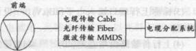
The cable TV system consists of three parts: front-end system, transmission system and cable distribution system.
3.1 Frontend
A combination of equipment located between the signal source and the transmission system that performs various technical processing on the transmission signal. It is the center of system signal processing. The performance of the front-end equipment plays a decisive role in the signal quality of the entire system.
3.2 Transmission system
For very large or large catv systems, the transmission system refers to the super trunk or trunk line for long-distance transmission. It is located between the front-end system and the cable distribution system. The technical requirement for the trunk system is to transmit the front-end signal to the cable distribution system connected to each trunk distribution point. At the same time, the requirements of carrier-to-noise ratio and nonlinear distortion must be met. The transmission system generally adopts three ways of cable, optical fiber or microwave multi-channel mmds.
3.3 Cable distribution system
It is located between the transmission system and the user terminal equipment, and amplifies and distributes the signal transmitted by the front end through the trunk system. The signal is evenly distributed to each user, and each user terminal is given a predetermined level. At the same time, each user terminal has good mutual isolation and does not interfere with each other. For the two-way cable TV system, it must also meet the technical requirements of the reverse return channel.
4 Transmission technology of cable TV system
4.1 Cable transmission technology
1. Composition of cable transmission system
The cable transmission system uses a coaxial cable as a transmission line, forming a trunk or super trunk of the catv network. The cable transmission system is mainly composed of the coaxial cable and the trunk amplifier interval configuration and cascade connection. The auxiliary equipment has an over-current type brancher and distributor for trunk line branching. The power supply and power interposer are used to supply power to the cable core of the mains amplifier.
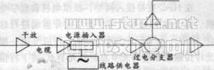
Schematic diagram of cable transmission trunk
2. Transmission characteristics and compensation of the cable
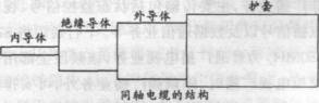
(1) Structure of coaxial cable:
The coaxial cable is composed of an inner conductor, an outer conductor, and an insulating medium in between. Commonly used are: lotus core type, closed slub type and physical foam type.
(2) Transmission characteristics of coaxial cable:
a. Characteristic impedance: 75 ohms
b. Attenuation characteristics: high frequency attenuation is greater than low frequency attenuation. The attenuation of the thin-core cable is greater than that of the thick-core cable. The attenuation is proportional to the cable length.
c. Temperature characteristics: As the temperature increases, the attenuation of the cable increases. The temperature coefficient of a general cable is about 0.2% / degree.
d. Shielding characteristics: The high-quality cable outer conductor has a good shielding effect, and the transmitted signal is not interfered by the outside world, nor will it radiate outwards or interfere with other signals. The shielding characteristic of the coaxial cable is expressed by the shielding attenuation, and the unit is db.
e. Mechanical properties: including bending resistance, moisture resistance, corrosion resistance and structural stability.
(3) Balance and compensation of cable transmission characteristics:
Because the attenuation of the coaxial cable is proportional to the length of the cable, the trunk line needs to be transmitted over a long distance, and the transmission characteristics of the cable must be compensated. The trunk amplifier is used to compensate the attenuation of the signal level by the cable, and to balance the frequency characteristics and temperature characteristics of the cable. Trunk amplifiers use amplifiers with the same characteristics, and the input and output level values ​​of each amplifier are the same. Adopt "unit gain method" design.
3. Restrictions on long-distance transmission
The coaxial cable transmission system uses trunk amplifier cascading to achieve long-distance transmission of TV signals. The longer the transmission distance, the greater the cascade connection n of the amplifier and the more the system index decreases.
With the development of regional cable television network construction, the transmission distance of the trunk transmission system is getting larger and larger, and the increase of amplifier cascade leads to the accumulation of noise, frequency distortion and nonlinear distortion, which makes the signal index drop. Moreover, the temperature characteristics of the cable increase the complexity of the system equipment, and the reliability is poor when transmitted over a long distance. The maintenance and management tasks of the system are heavy, and the service level is difficult to improve.
4.2 Microwave multi-channel mmds transmission technology
1. Technical characteristics of mmds
(1) Definition of multi-channel microwave distribution system mmds: use microwave frequency to transmit at one point and multi-point reception to transmit TV, sound broadcasting and data signals to each cable TV station, common antenna TV system front end or directly to each user's Microwave system.
(2) Frequency range: space transmission 2500-2700mhz
Receive allocation 111-750mhz
(3) Transmission mode: The multi-channel microwave signal adopts the space transmission mode. The transmission and reception should be within the line of sight.
2. The composition of the mmds transmission system: consists of a transmission system and a reception system. The equipment of the transmission system includes a transmitter, a synthesizer, a feeder cable, and a transmission antenna; the equipment of the reception system includes a reception antenna, a down converter, and a power supply.
3. Limitations of wireless transmission defects
The mmds transmission system is a wireless transmission, with the common shortcomings of wireless transmission, such as signal fear of occlusion, reflection of ghosts, and susceptibility to interference. This method is not suitable for large and medium-sized cities with dense population and high-rise buildings.
4.3 Optical fiber transmission technology
1. Characteristics of optical fiber transmission technology
(1) The optical fiber transmission loss is small, which can realize the long-distance trunk transmission of the TV signal and ensure the technical index of the TV signal.
The coaxial cable used for the trunk line in the catv system, even if it is very thick (such as the US mc750 cable), the loss at 750mhz must be about 40db / km. The optical signal with a wavelength of 1310nm has a loss of about 40db / 100km. The loss of optical fiber is 100 times lower than that of coaxial cable. Obviously, replacing the coaxial cable trunk line with an amplifier every few hundred meters by using optical fiber can achieve direct transmission across dozens of kilometers. It completely solves the problem that the transmission signal cascading causes the transmission signal technical index to drop.
(2) The optical fiber frequency bandwidth can ensure that multiple channels of cable TV signals are transmitted to each optical node in a balanced manner.
(3) The optical fiber without relay has a long transmission distance, strong anti-interference ability, and high system reliability.
(4) Optical fiber transmission technology is not limited to the transmission of cable TV signals. It provides an open platform for the development of broadband integrated service transmission and is an important part of the broadband integrated service network.
2. Composition of optical fiber transmission system
The most basic optical fiber transmission system is composed of electro-optic converter (e / o), optical fiber and photoelectric converter (o / e). Also called optical link. The optical fiber transmission system has a large transmission capacity, and multiplexing transmission is implemented in the system.
(1) Air division multiplexing: (sdm). (One fiber for each top and bottom)
(2) Time division multiplexing: (tdm).
(3) WDM: (wdm).
(4) Subcarrier multiplexing: (scm).
3. Provide an open platform for broadband integrated service transmission
Optical fiber cable network is not only limited to cable TV services, it can provide an open platform for the development of broadband integrated service transmission and is an important part of the broadband integrated service network. The use of optical cables to form a wide area multimedia network, including TV services, has broad prospects.
4.4 Fiber-optic coaxial hybrid network-topological structure of hfc broadband access network
The hfc cable television network consists of optical fiber as the trunk line and coaxial cable as the distribution network to form a fiber-optic coaxial hybrid network. It gives full play to the excellent characteristics of optical fiber and cable, and organically combines to complete the high-quality transmission and distribution of cable TV signals. This constitutes this unique fiber / coax hybrid network structure. HFC is a fiber-optic star layout centered on the front end, extending from the optical fiber to the cell and ending at the optical node, and at the same time, extending from the optical node to cover users with a star tree coaxial cable network. Therefore, the hfc cable TV network topology is a star-tree structure.
In the hfc broadband access network, analog TV and digital TV, and integrated data service signals are integrated at the front end or sub-front end, and a downlink optical transmitter is used to transmit the downlink signal to the corresponding optical node with a fiber. At the optical node, the downlink signal is converted into a radio frequency signal. Each optical node uses a coaxial cable to cover users in a star tree topology. The upstream signal from the user is converted into an upstream optical signal at the optical node, and then transmitted back to the front end or sub-front end through the upstream optical transmitter and upstream return fiber. The uplink and downlink signals use space division multiplexing in optical transmission and frequency division multiplexing in cable transmission.
The HFC network uses frequency division multiplexing technology to divide the 5-1000mhz frequency band into uplink and downlink channels. 5-65mhz is the upward channel, 87-1000mhz is the downward channel. The upstream channel is a non-broadcast service, and its main transmission includes status monitoring signals, video-on-demand signals, and data communication services. Downstream channel will be 87-550mhz for ordinary broadcast TV service. When this frequency band is used for analog TV broadcast, in addition to FM broadcast service, analog TV programs of about 54 channels can be arranged. 550-750mhz is a downlink digital communication channel used to transmit digital broadcast TV, vod digital video, and digital phone downlink signals and data. The uplink data generally uses the 5-65mhz frequency band. In order to improve anti-interference ability, qpsk (or 16qam) modulation is used.
Cable TV hfc online integrated digital services rely on cable modem cable modem and set-top-box. The cable modem system consists of a cable modem (cm) placed at the user end and a cmts (cable modem termination system) placed at the front end. The basic function of the user terminal cm is to modulate the upstream digital signal into an rf signal and demodulate the downstream rf signal into a digital signal. The main advantages of the hfc access network are: huge access bandwidth, which can provide various analog and digital services; the high downlink rate of the cable modem system is a significant advantage, which improves the utilization of network resources; at the same time, it also has a permanent online 1. The advantage of no dialing.
The main services of the cable TV access network can be divided into two categories, namely broadcast TV services and interactive services. Radio and TV services include the transmission of current analog TV programs and other broadcasting services such as digital broadcasting and digital TV that are gradually developing. Interactive services include internet access, video-on-demand vod, videophone, conference TV, distance education, and remote medicine.
5. Cable TV cable transmission network
As part of the cable TV metropolitan area network, the cable television cable transmission network has undergone great changes in planning and design, design standards, technical indicators, and construction process specifications. The cable TV cable transmission network is no longer the same as before: each cell has its own system, with a front end for receiving TV signals, transmission lines and a distribution network in the building. It belongs to a closed, small and independent shared antenna system. Today's cable transmission network does not need a front end. To build a two-way transmission broadband network, it must not only meet the relevant national standards, but also implement the overall technical requirements of the local cable TV network.
5.1 Implementation of two-way transmission:
In the hfc access network, in order to realize the bidirectional transmission of signals, space division multiplexing, frequency division multiplexing and time division multiplexing technologies are adopted at the same time. In the optical fiber transmission link from the optical node to the front end (or the sub-front end of the backbone network), the upstream and downstream signals are spatially multiplexed: from the optical node to the user's cable network, the upstream and downstream signals are frequency division multiplexed, and the data is transmitted Using time division multiplexing,
5.2 The noise of the return channel
In the hfc network, the aggregate noise of the reverse channel is the main problem affecting the two-way data transmission. Due to the large reverse noise, the c / n of the data transmission link is greatly reduced. Therefore, solving the noise problem of the reverse return channel is the key to the smooth development of two-way services in the â…²c network.
The noise collected in the upstream channel comes from many forms. Among them, the main influence on the uplink signal transmission is the signal's clipping distortion, network structure noise and intrusive noise.
(1) Clipping distortion is mainly caused by the nonlinear distortion of the transmission equipment such as reverse return optical transmitter and bidirectional amplifier in the system.
(2) The structural noise mainly comes from the basic thermal noise generated by the devices of the active equipment in the system. At the same time, due to the cascade of amplifiers and the collection of return signals from each branch, the power of the noise is superimposed, forming a "funnel effect."
(3) Intrusive noise is mainly caused by the intrusion of external electromagnetic waves. It is a random and irregular radio frequency interference. It is a technical problem that hfc network needs to overcome to carry out two-way data communication. There are two main types of intrusive noise in the system, namely: a narrow-band short-wave signal interference: b impulse pulse interference: mainly including pulse interference generated by lightning, motors, engines, and household appliances.
5.3 Composition of cable distribution network
1. Transmission system
Including the positive and reverse rf amplification mode in the optical node, bidirectional extension amplifier, line splitter, distributor, power supply, coaxial cable, etc. The forward optical receiver in the optical node converts the downstream optical signal into an electrical signal, and then it is amplified to a higher level by the rf broadband amplifier placed in the optical node, and then extended by the extension amplifier, coaxial cable and line on the extension line. Branches and distributors distribute the signal downstream to each distribution system. From the distribution, the system returns the upstream signal in the reverse direction, from the input port of the distribution amplifier along the forward transmission path to reverse rotation, through the coaxial cable, line splitter, distributor, extension amplifier, enter the optical node, send The person returns the laser.
2. Distribution system
Including bidirectional distribution amplifiers (ie floor amplifiers), splitter distributors, bidirectional user terminals and coaxial cables.
The extension line transmits the downstream signal to the input of each distribution amplifier. After the distribution amplifier amplifies the signal to the required level, it is transmitted to each user terminal through the coaxial cable, distributor, and splitter. Reverse return upstream signal from the user, from the return transmitter of the user application equipment, back to the user terminal through the user cable, through the brancher, distributor and coaxial cable, to the output end of the distribution amplifier, through the distribution amplifier Amplify to an appropriate level and send it to the transmission system from the input of the distribution amplifier.
5.4 Planning and design of cable distribution network
As the network planning of residential districts is restricted by civil construction planning, the civil design of residential houses of various styles is very different, and the buildings are different in size, height and shape. In particular, the layout of building groups in each community is different. Therefore, there is no possibility of a unified model for network planning in residential quarters, which can only be adapted to local conditions.
1 Position of optical node
The optical node should be installed in the central building of the service area to achieve the purpose of minimizing the longest distance of the extension cable transmission and reducing the cascading of the extension amplifier. In turn, the noise and nonlinear distortion of the transmitted signal are reduced.
2 Division of optical node service area
According to the number of users in each building, similar buildings should be composed of about 500 service areas. Since the number of users in buildings with different structures varies greatly, it is not appropriate to divide the service area according to the number of buildings.
3. Equipment selection
(1) Selection of coaxial cable
All cables in the system use physical foam cables. For the extension cable, a 12 cable with an aluminum tube as the outer conductor should be selected. All outer cable adopts stable polyethylene outer sheath.
(2) Extension amplifier
Since the service area of ​​the optical contact is not too large, the manual gain control amplifier (mgc) can meet the use requirements. The extension amplifier differs according to the module used. There are push-pull amplifiers and power multiplying amplifiers. Extension amplifiers should generally use dual-module power multiplying amplifiers.
4. Upstream and downstream channel structure of bidirectional amplifier
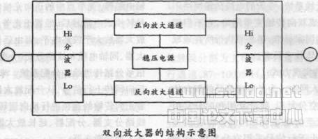
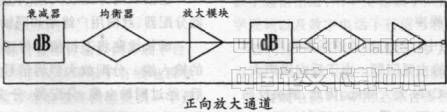
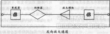
The bidirectional amplifier is generally composed of a forward amplification channel, a reverse amplification channel, a demultiplexer, a mixer, and a regulated power supply.
The forward amplification channel is composed of a front attenuator and equalizer, a first-stage amplification module, an inter-stage attenuator and an equalizer, and a second-stage amplification module.
The reverse amplification channel is composed of a reverse amplification module, an attenuator and an equalizer.
5. Design calculation formula
(1) The relationship between the carrier-to-noise ratio of the output signal of the amplifier and the noise figure:
c / n = si-nf-2. 4
Where: si is the amplifier input level
nf is the noise figure of the amplifier
(2) Carrier-to-noise ratio after cascading of amplifiers (the working state of amplifiers at all levels is the same)
(c / n) n = (c / n) 1-10lgn where: n is the number of cascades
(3) The c / ctb of the amplifier depends on the output of the amplifier
Level, when the output level increases ldb, c / ctb drops 2db.
(4) c / ctb after amplifier cascading (the working state of amplifiers at all levels is the same)
(c ï¼ ctb) n = (c ï¼ ctb) 1-20lgn
Where: n is the number of cascades
5.5 User Distribution Network
1 The composition of a residential building (building) user distribution network As a distribution system in a residential community network, it mainly includes user distribution amplifiers (ie, floor amplifiers), coaxial cables, branch distributors, and user terminals.
2 Equipment used by user distribution network
(1) Bidirectional user distribution amplifier
Adopt dual-module power multiplier type or dual-module push-pull type.
(2) Distributor and brancher
Both the distributor and the splitter are passive network equipment, and their main functions are to distribute power to downstream signals and to aggregate upstream signals.
The distributor divides the downlink signal into several channels evenly, and plays a role in the downlink channel. Commonly used are two distributors (divided into two channels), three distributors (divided into three channels), four distributors (divided into four channels), and six distributors (divided into six channels).
The splitter divides the downstream signal unevenly into several channels, and the output signal has a main channel output and a branch output. Main channel output attenuation is small, and redistribution can be continued. The branch output has a series of attenuations for selection during signal distribution. At the same time, the reverse return signals of the main output terminal and the branch output terminal are collected. Commonly used are one-branch, two-branch, three-branch, four-branch and six-branch.
The main performance indicators of the distributor
a. Distribution attenuation: refers to the difference between the input level of the input end of the distributor and the output level of the output end. The more distributors, the greater the distribution attenuation.
b. Mutual isolation: refers to the isolation between the output terminals of the distributor. Mutual isolation characterizes the degree of mutual influence of each output of the distributor. The larger the value of mutual isolation, the smaller the mutual influence.
c. Port impedance and reflection loss
All equipment in the cable TV system uses a 75-ohm port impedance. Reflection loss is a measure of the degree of port impedance matching of various devices. The larger the value of the reflection loss, the better the impedance matching.
Main performance indicators of the splitter
a. Branch attenuation: refers to the difference between the input level of the input end of the branch and the output level of the branch output.
b. Reverse isolation: refers to the isolation between the branch output of the branch and the main output. Reverse isolation characterizes the degree of mutual influence between the branch output of the branch and the main output. The greater the reverse isolation, the smaller the mutual influence.
c. Insertion loss: refers to the difference between the input level of the splitter input and the output level of the main output. The smaller the branch attenuation of the splitter, the greater the insertion loss.
d. Port impedance and reflection loss: same as distributor.
(3) Coaxial cable
The cables used in the distribution system are all physical foam coaxial cables. The -5 cable is used for the connection between the splitter, distributor and user terminal. For the distributor connected to the output end of the distribution amplifier, the shunt cable distance at the output end is longer, and -7 or -9 cables should be used. In order to reduce the noise of the return channel, four shielded cables should be used.
Sijee Fiber optic adaptors are part of passive components for FTTH ODN connectivity, Sijee Fiber optic adaptors are used to join two fiber optic patch cables together for realizing the transition between different interfaces and they are available for use with either single-mode or multimode Fiber Optic Patch Cord. Sijee Fiber optic adaptors can offer superior low loss performance with very high repeatability.
Sijee offers different types of fiber adaptors comply with ITU standard, main products including Fiber Mating Sleeve Adaptor, Fiber Hybrid Adaptor, Fiber Bare Fiber Adaptor , Fiber Mechanical Attenuator, Field Assembly Optical Connector (FAOC), Splice-On Connector, Semi-finished Fiber Connector, etc.
Optical Fiber Couplers,Optical Fiber Adapter,Fiber Optic Adapter, Fiber Optic Flange are available.
Features:
1. Compliant with: IEC, JIS, Telcordia
2. Convenience and ease of handling
3. Optical performance 100% factory tested
4. Flange or threaded mounting type
5. Ceramic/Zirconia or phosphorous bronze sleeves
6. Good changeability and repeatability
Applications:
1. Telecommunication networks
2. FTTX, FTTH
3. LAN, WAN, CATV networks
4. Fiber communications, Data communication networks and processing, Industrial, Mechanical and Military.
5. Active device termination


Fiber Adaptor
Optical Fiber Couplers,Optical Fiber Adapter,Fiber Optic Adapter,Fiber Optic Flange
Sijee Optical Communication Technology Co.,Ltd , https://www.sijee-optical.com