Ultrasonic distance measurement circuit design
Due to the strong directivity of ultrasonic waves, slow energy consumption, and the long distance of propagation in the medium, ultrasonic waves are often used for distance measurement, such as rangefinders and level measuring instruments. The use of ultrasonic testing is often relatively fast, convenient, simple calculation, easy to achieve real-time control, and can meet the industrial practical requirements in terms of measurement accuracy, so it has also been widely used in the development of mobile robots.
In order for the mobile robot to walk automatically while avoiding obstacles, it must be equipped with a distance measuring system so that it can obtain distance information (distance and direction) from obstacles in time. The three-direction (front, left, and right) ultrasonic ranging system introduced in this article is to provide the robot with a range of motion distance information to understand the environment in front of it, left, and right.
Principle of Ultrasonic Ranging
1. Ultrasonic generator
In order to study and use ultrasound, many ultrasound generators have been designed and made. Generally speaking, ultrasonic generators can be divided into two categories: one is to generate ultrasonic waves by electrical means, and the other is to generate ultrasonic waves by mechanical means. The electrical methods include piezoelectric type, magnetostrictive type and electric type, etc .; the mechanical methods include Galton whistle, liquid whistle and air flow whistle. The frequency, power and sound wave characteristics of the ultrasonic waves generated by them are different, so their uses are also different. At present, the piezoelectric ultrasonic generator is more commonly used.
2. The principle of piezoelectric ultrasonic generator
The piezoelectric ultrasonic generator actually uses the resonance of the piezoelectric crystal to work. The internal structure of the ultrasonic generator is shown in Figure 1. It has two piezoelectric wafers and a resonance plate. When a pulse signal is applied to its poles and its frequency is equal to the natural oscillation frequency of the piezoelectric wafer, the piezoelectric wafer will resonate and drive the resonance plate to vibrate, which generates ultrasonic waves. Conversely, if no voltage is applied between the two electrodes, when the resonance plate receives ultrasonic waves, it will press the piezoelectric wafer to vibrate and convert mechanical energy into electrical signals. At this time, it becomes an ultrasonic receiver.
3. The principle of ultrasonic ranging
The ultrasonic transmitter emits ultrasonic waves in a certain direction, and starts timing at the same time as the transmission time. The ultrasonic waves propagate in the air. When an obstacle is encountered on the way, it returns immediately. When the ultrasonic receiver receives the reflected wave, it immediately stops timing. The propagation speed of ultrasonic waves in the air is 340m / s. According to the time t recorded by the timer, the distance (s) from the launch point to the obstacle can be calculated, that is: s = 340t / 2
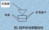
Figure 1 Ultrasonic sensor structure
This is the so-called time difference ranging method.
Circuit design of ultrasonic ranging system

Figure 2 Schematic diagram of ultrasonic ranging circuit
The characteristic of this system is to use the single-chip microcomputer to control the transmission of ultrasonic waves and the timing of the round-trip time from the transmission of the ultrasonic waves to the receiving. The circuit schematic is shown in Figure 2. Only the wiring diagram of the front ranging circuit is drawn. The left and right ranging circuits are the same as the front ranging circuit, so they are omitted.
1. 40kHz pulse generation and ultrasonic emission
The ultrasonic sensor in the ranging system uses the piezoelectric ceramic sensor of UCM40, and its working voltage is a pulse signal of 40 kHz, which is generated by the single-chip microcomputer executing the following procedure.
puzel: mov 14h, # 12h; ultrasonic emission lasts 200ms
here: cpl p1.0; output 40kHz square wave
nop;
nop;
nop;
djnz 14h, here;
ret
The input terminal of the front ranging circuit is connected to the P1.0 port of the single-chip microcomputer. After the above program is executed, the single-chip microcomputer outputs a 40kHz pulse signal at the P1.0 port. After being amplified by the transistor T, the ultrasonic transmitter UCM40T is driven to emit 40kHz pulsed ultrasonic waves. And continue to transmit for 200ms. The input terminals of the right and left ranging circuits are connected to P1.1 and P1.2 ports respectively, and the working principle is the same as that of the front ranging circuit.
2. Reception and processing of ultrasonic waves
The receiving head adopts UCM40R paired with the transmitting head, which transforms the ultrasonic modulation pulse into an alternating voltage signal, which is amplified by the two poles of the operational amplifiers IC1A and IC1B and added to IC2. IC2 is an audio decoding integrated block LM567 with a locking loop. The center frequency of the internal voltage-controlled oscillator f0 = 1 / 1.1R8C3, and the capacitor C4 determines its locking bandwidth. Adjust R8 on the carrier frequency of the launch, then the input signal of LM567 is greater than 25mV, the 8 pin of the output end changes from high level to low level, as an interrupt request signal, it is sent to the microcontroller for processing.
The output of the front ranging circuit is connected to the INT0 port of the single-chip microcomputer, and the interrupt priority is the highest. The output of the left and right ranging circuits is connected to the INT1 port of the single-chip microcomputer through the output of the AND3 IC, and the P1.3 and P1.4 of the single-chip microcomputer are connected to the input of the IC3A. At the end, the identification of the interrupt source is handled by the program query, and the interrupt priority is first right then left. Some source programs are as follows:
receive1: push psw
push acc
clr ex1; turn off external interrupt 1
jnb p1.1, right; P1.1 pin is 0, go to the right ranging circuit interrupt service program
jnb p1.2, left; P1.2 pin is 0, go to the left ranging circuit interrupt service program
return: SETB EX1; open external interrupt 1
pop? acc
pop? psw
reTI
right: ...?; Right ranging circuit interrupt service program entry
? ajmp? return
left: ...; the entrance of the left ranging circuit interrupt service program
? ajmp? return
3. Calculate the ultrasonic propagation time
Start the timer T0 inside the single-chip microcomputer at the same time as starting the transmitting circuit, and use the counting function of the timer to record the time of ultrasonic wave transmission and the time of receiving the reflected wave. When the ultrasonic reflected wave is received, a negative transition is generated at the output of the receiving circuit, and an interrupt request signal is generated at the INT0 or INT1 terminal. The microcontroller responds to the external interrupt request, executes the external interrupt service subroutine, reads the time difference, and calculates the distance. Part of its source program is as follows:
RECEIVE0: PUSH PSW
PUSH ACC
CLR EX0; turn off external interrupt 0
? MOV R7, TH0; read time value
MOV R6, TL0?
CLR C
MOV A, R6
SUBB A, # 0BBH; calculate the time difference
MOV 31H, A; store results
MOV A, R7
SUBB A, # 3CH
MOV 30H, A?
SETB EX0; open external interrupt 0
POP ACC?
POP PSW
RETI
4. Software design of ultrasonic ranging system

The software is divided into two parts, the main program and the interrupt service program, as shown in Figure 3 (a) (b) (c). The main program completes the initialization work and the control of the ultrasonic transmission and reception sequence of each channel.
The timer interrupt service subroutine completes the three-way ultrasonic emission in turn. The external interrupt service subroutine mainly completes the reading of time values, distance calculation, and output of results.
V. Conclusion
Many measurements have been made on the plane objects within the required measurement range of 30cm ~ 200cm, and the maximum error is 0.5cm, and the repeatability is good. It can be seen that the ultrasonic ranging system based on the single-chip microcomputer has the characteristics of simple hardware structure, reliable operation and small measurement error. Therefore, it can be used not only in mobile robots, but also in other detection systems.
Laptop power adapter charger for Dell:
| Laptop Model | Adapter Output |
| Latitude E5400 E5410 E5500 E5510 | 19.5v 4.62a, 7450 |
| Studio XPS 16 (1645)1640 1645 1647 | 19.5v 4.62a, 7450 |
| Studio XPS M1645 M1647 | 19.5v 4.62a, 7450 |
| XPS 14 15 17 L501x L502x L702x L702x | 19.5v 4.62a, 7450 |
| Inspiron 1464 1564 1764 | 19.5v 4.62a, 7450 |
| Inspiron 1525 1440 1526 | 19.5v 3.34a, 7450 |
| Precision M4600 M6600 | 19.5v 6.7a, 7450 |
| Inspiron N5050 N4010 N5110 | 19.5v 3.34a, 7450 |
| Inspiron 14Z-N411Z 13Z N311Z | 19.5v 4.62a, 7450 |
| Inspiron 1545 | 19.5v 3.34a, 7450 |
| Latitude E5420 E5530 E5430 E6420 | 19.5v 4.62a, 7450 |
| Inspiron 1440 1525 1526 1545 1750 | 19.5v 3.34a, Octagon tip |
| Inspiron 1300 B120 B130 | 19v 3.16a/3.42, 5525 |
| Inspiron 1525 1526 1545 | 19.5v 3.34a, 7450 |
| Studio 1440 1440n 1440z 14z 14zn | 19.5v 3.34a, 7450 |
| Latitude E4300 E4310 | 19.5v 4.62a, 7450 |
| Inspiron 13Z 13ZD 13ZR M301 M301z M301ZD M301ZR N301 | 19.5v 3.34a, 7450 |
| Inspiron N301Z N301ZD N301ZR | 19.5v 3.34a, 7450 |
| Studio 1535 1536 1555 1557 1558 | 19.5v 4.62a, 7450 |
| Latitude E5420 E5520 E6430 E6530 E6420 E6520 | 19.5v 4.62a, 7450 |
| Inspiron Mini 10 10v 1010 1010n 1010v 1011 1011n 1011v | 19v 1.58a, 5517 |
| Inspiron 14V 14VR M4010 N4020 N4030 | 19.5v 4.62a, 7450 |
| Inspiron N4110 N5110 N7110 M5010 | 19.5v 3.34a, 7450 |
| 630M 640M E1405 | 19.5v 4.62a, 7450 |
| Inspiron 15-3521 17-3721 | 19.5v 3.34a, 7450 |
| Latitude 120L | 19.5v 3.34a, 7450 |
| Vostro 1710 1710n 1720 1720n | 19.5v 4.62a, 7450 |
| Vostro 1500 1700 Inspiron 1520 1521 1720 | 19.5v 4.62a, 7450 |
| Vostro 1400 1420 PP26L | 19.5v 3.34a, 7450 |
| Latitude D410 | 19.5v 3.34a, 7450 |
| Inspiron 1120, 1121, M101 | 19.5v 3.34a, 7450 |
| Inspiron Mini 1012 1018 | 19v 1.58a, 5517 |
Our service:
Stable output and high charging efficiency.
Elegant outlook design as original one, touch smoothly and comfortable.
Original charger is good, but as a replacement, our product has more reasonable price when your original charger is broken.
And, the market of the replacement adapters becomes bigger and bigger. People would rather buy a copy one then the original because of the price.
But at the same time, people worry about that they will buy something defective. So the problem comes, how to buy a good quality one with a good price?
As a professional power adapter manufacturer, we have excellent R&D team, skilled staffs and responsible after-sale service. All your benefits can be under protected after you buy products for our company.
Our certificates :ISO9001:2008 & ISO14001:2004 , CCC , CE , FCC , ROHS.
All our products has 1 year warranty. In other words, if you get the dad products which are not damaged physically from us in one year, we will replace you the new one or the whole bulk order.
Mini Charger For Dell,Big Connector Adapter,45W Power Adapter,Dell Computer Adapter
Shenzhen Waweis Technology Co., Ltd. , https://www.waweis.com