Design of USB interface circuit using P89C61x2 and ISP1581
Abstract: This article mainly introduces the method of using P89C61x2, ISP1581 chip to design and test the USB interface of the system, expounds the design flow of hardware, software, applications, etc., and realizes a simple and reliable connection and communication between the host and the device during the test .
Keywords: USB; interface chip; firmware, P89C61
This paper mainly designs an interface circuit based on single chip microcomputer for the parallel interface of traditional instruments.
Main chip introduction This design uses the control chip P89C61x2 and the interface chip ISP1581 to realize the design of the USB interface circuit.
P89C61x2 includes 1024B RAM, 64KB Flash memory, 32 I / O ports, 3 16-bit positioning / counters, 6 interrupt sources-4 interrupt priorities-nested interrupt structure, 1 enhanced UART, on-chip oscillation And clock circuit. In addition, the static design of the device makes it have a very wide frequency range, you can choose 1MHz ~ 12MHz crystal oscillator. There are two software-selectable power-saving modes-idle mode and power-down mode.
The USB interface chip ISP1581 is a low-cost, powerful USB interface device that complies with the USB2.0 specification and provides high-speed USB communication capabilities for systems based on microcontrollers or microprocessors; with 7 IN endpoints and 7 OUT endpoint and a fixed control IN / OUT endpoint; can be connected to the USB bus through software control; internally integrated 12MHz crystal oscillator with PLL; can be reset by internal power-on reset, low voltage reset circuit and software.
The connection block diagram of the system hardware design system is shown in Figure 1.
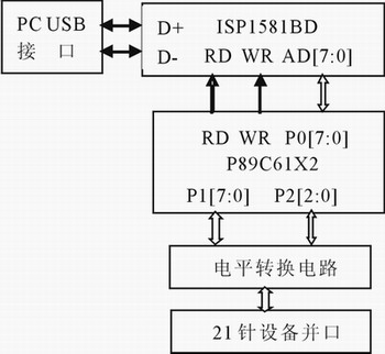
Figure 1 System connection diagram
ISP1581 has two working modes: general processor working mode and disconnected bus working mode. In the hardware design of this paper, the working mode of disconnecting the bus is realized by setting BUS-CONF = 0. AD [7: 0] is an 8-bit multiplexed address / data, connected to the P0 port of the microcontroller; DATA [15: 0] is a 16-bit data bus. MODE0 connects to high level, indicating that the read or write signal works in the 8051 type; ALE is connected to the ALE of the microcontroller to implement address latching; RPU is the external pull-up resistor connection terminal of the USB D + line, through a 1.5kW resistor and Vcc (3.3 V) Connected; RREF is connected to an external bias resistor and connected to the ground through a 12.0kW resistor, so that the high-speed transceiver gets an accurate mirror power supply. In order to achieve good EMC characteristics, all power pins are connected to the network with 0.01mF and 0.1mF capacitors in parallel.
System firmware design The firmware of the single chip microcomputer is the core of the USB device operation. It mainly includes the following parts:
Kernel.c: scan USB events cyclically; start the work of devices and systems;
Isr.c: interrupt service routine;
Chap9.c: Contains standard USB commands for establishing a basic connection between the device and the host;
Vendor.c: Contains vendor-defined commands and processes vendor requests;
Init.c: Initialize the MCU and ISP1581 chip.
The initialization program mainly initializes various state variables, including the initialization of the single-chip microcomputer and the setting of the ISP1581 register. It mainly includes address register, mode register, interrupt configuration register, interrupt enable register and endpoint register.
The USB device uses control transfer to complete the enumeration, thereby judging the status of the device.
The data transmission process uses an interrupt mode. The microcontroller determines the interrupt source by reading the status of the interrupt register and enters the corresponding interrupt handler. ISP1581 mainly includes SETUP interrupt, bus suspend interrupt and endpoint input / output interrupt, etc. The control endpoint sets a 64B buffer, which can only transmit 64B at a time, and the amount of data transferred is controlled by the single chip microcomputer. If the number of transmitted bytes is greater than 64B, 64B will be transmitted first, and then the remaining number of bytes will be determined, and at the same time, whether it is an empty packet or a short packet. If no data is transferred to the microcontroller, an empty packet will be sent to indicate that the data has been sent.
The firmware mainly completes device initialization, USB protocol standard request processing, and other application programs such as data exchange functions. The program is written in C51 language and compiled using Keil's uVision2 compiler.
The main loop of firmware is shown in Figure 2.
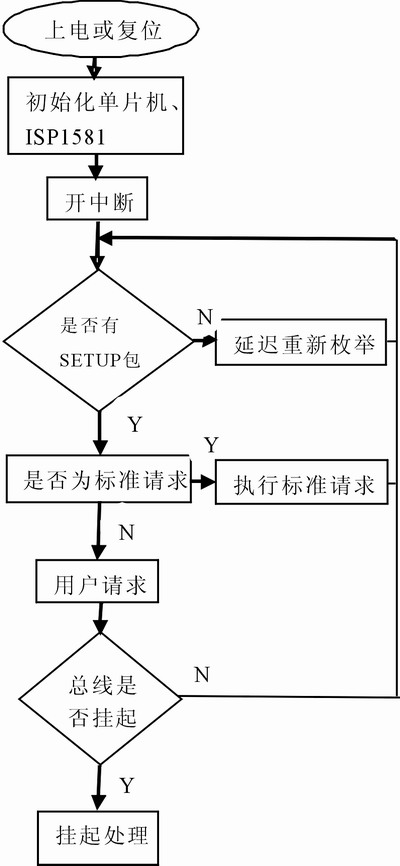
Figure 2 firmware program flow chart
Design of device drivers and applications
For the development of USB device drivers, Driver Works and Microsoft 2000DDK can be used, and VC ++ 6.0 is used as the development environment. In order to facilitate users to develop USB interface, a universal driver program is provided in the development package of DP-1581, which can be used directly without modification. In this circuit design, the driver that comes with the development version is used.
Conclusion This system improves the original parallel port to a USB interface, supporting plug and play and hot plug. The actual test proves that the performance of this system is stable and reliable, and it has certain practical application value.
references
1 Zhou Ligong. USB2.0 and OTG Specification and Development Guide. Beijing: Beijing University of Aeronautics and Astronautics Press, 2004
2 Xiao Shiwen. USB2.0 hardware design. Beijing: Tsinghua University Press, 2002
- Eco-friendly-mercury free, no radiation, low carbon
- Eye-protection: uniform and soft light effect, anti-dazzle, relieve visual fatigue
- LED high purity display calendar
- Superb light quality: high luminance light effect, high purity, high color rendering
- Energy-saving: low power consumption, low degradation, save up to 80% energy
- Efficient heat dissipation
- Long lifespan(more than 50, 000 hours)
Metal LED Desk Lamp,Dimmable LED Desk Lamp,Long Arm Metal LED Desk Lamp,Rechargeable Metal LED Desk Lamp
Shenzhen Superlight Technology Co., Ltd. , https://www.superlighttech.com