Design of Automobile Engine Automatic Test Bench
introduction
The Steyr diesel engine produced by Weifang Diesel Engine Factory has huge power and is one of the main power models widely used in China's heavy machinery and large trucks. In order to improve quality, each Steyr diesel engine undergoes rigorous performance tests before leaving the factory. According to the "factory inspection specifications", it mainly tests the temperature, pressure, power consumption and speed of each diesel engine under certain working conditions (throttle). And the power consumption, temperature, pressure and other indicators at a certain speed and torque. Design a heavy-duty automobile engine automation test bench, manage the computer through the test bench to form operation menus and test forms, and test commands, which are transmitted to each single-chip microcomputer measurement and control system. The test results are sent to the management computer for corresponding processing and display. Before the machine leaves the factory, it is rigorously tested by an automated test bench to check whether it meets the requirements of the factory inspection specifications. Diesel engines that meet the requirements can be tested and shipped out. Write a test analysis report for the diesel engines that do not meet the requirements based on the test data of the automated test bench The workshop makes rectifications and forms a technical file for each machine tested.
System composition
The diesel engine automation test bench is composed of management computer, CAN bus, temperature measurement and control single-chip system, pressure measurement and control single-chip system, speed measurement and control single-chip system, power consumption measurement and control single-chip system, as shown in Figure 1. The hardware design principle of various single-chip microcomputer test systems is that when changing the software control scheme or adding other functions, there is no need to replace the hardware or make minor changes; the operation is stable and reliable, with a high cost performance; the operator can easily adjust various parameters. The management computer is equipped with a PCI bus PCAN bus conversion card. The software realizes data storage and user operation interface by VB and Access database. The computer simulation software uses SIMULINK software package. It is an extension of MATLAB software and can establish an intuitive system model. This system model can be dynamically established and modified with the SIMULINK software package, and connected to the test system via VB in real time. This is very convenient for the trial production of diesel engines and finding the cause of failures. 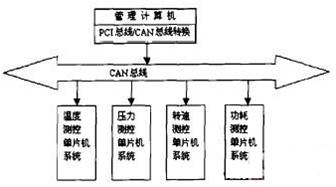
Figure 1 System composition
The model data of the system is transferred to each MCU measurement and control system via CAN bus.
CAN bus
Any node on the CAN network is allowed to send information as the master node. Any node can actively send information to other nodes at any time. It supports point-to-point, point-to-multipoint and global broadcast to receive and send data. The communication medium uses 120Ω twisted pair, the communication rate can reach 1Mbps, and the information is transmitted according to the priority level in units of frames, which is suitable for occasions with high real-time requirements. The CAN bus driver uses PCA82C250, which uses differential transmission and differential reception. PCA82C250 has two signal output terminals CANH and CANL. The two states of the CANH terminal are high level and high resistance state, and the two states of the CANL terminal are low level and high resistance state. Therefore, the distributed control system formed by it, even if multiple nodes send data to the network at the same time, there will not be a short-circuit phenomenon like RS485.
Temperature measurement and control single chip system
The temperature measurement and control singlechip system is shown in Figure 2. 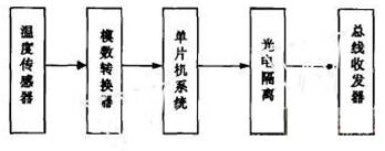
Figure 2 Temperature measurement and control single chip system
The temperature sensor adopts platinum resistance and performs temperature calibration. The analog-to-digital sensor uses the 12-bit APD sensor AD678, which has high-speed signal acquisition for AC and DC signal characteristics. The chip contains a sample P-hold amplifier circuit, a bus interface compatible with a microprocessor, a reference voltage source, and clock generation Device. The one-chip computer adopts P835C91VFA chip, which has CAN controller, CAN receive interrupt, extended acceptance filter, multi-host structure, information identification code (11-bit or 29-bit) to determine the bus access priority. Add high-speed optocoupler 6N137 between CAN bus transceiver PCA82C250 and CAN controller for isolation to improve anti-interference ability.
Single-chip microcomputer system for pressure measurement and control
The hardware difference between the pressure measurement and control single-chip system and the temperature measurement and control single-chip system is that the sensors used are different, and the pressure sensors use pressure strain gauge sensors.
Speed ​​measurement and control single chip system
At present, the speed sensor is developing in the direction of high sensitivity, high reliability and full integration. The speed measurement and control single-chip system uses the KMI15 series magnetoresistive integrated speed sensor produced by Philips. The sensor has excellent performance, safety and stability. KMI15-1 chip contains high-performance magnetic steel, magnetoresistive sensor and IC. It uses the IC to complete the signal conversion function. The frequency of the current signal output is proportional to the measured speed, and the amplitude of the current signal changes from 7mA to 14mA. Because its peripheral circuit is relatively simple, it is easy to match the secondary instrument to measure the speed. The KMI15-1 device has a wide measurement range and high sensitivity. Its gear rotation frequency range is 0 to 25 kHz, and it can measure even when the rotation frequency is close to zero. The maximum magnetic induction distance between the sensor and the gear is 2.9mm (typical value). Because it is far away from the gear, it is safe to use. The sensor has strong anti-interference ability and has directionality, and it is not sensitive to axial vibration. In addition, there are electromagnetic interference (EMI) filters, voltage controllers and constant current sources inside the chip, thus ensuring that its operating characteristics are not affected by external factors.
The size of KMI15-1 is small, and its maximum external dimension is 8 × 6 × 21mm, which can be reliably fixed near the gear.
KMI15 adopts + 12V power supply (typical value), and the maximum is not more than 16V. The working temperature range is as wide as -40 ~ + 85 ℃.
The simplified circuit of the sensor is shown in Figure 3. 
Figure 3 Sensor simplified circuit
The frequency of the current signal output from U2 is proportional to the measured speed. The rotational speed can be determined by counting through the single chip microcomputer.
Single-chip system for power consumption measurement and control
The power consumption measurement and control single-chip system uses the signal collected by the torque sensor to obtain the power consumption under a certain working condition after processing and speed calculation. The software installed in various single-chip test systems is different.
PCI bus / CAN bus conversion card
The PCI bus / CAN bus conversion card is a PC smart board based on the PCI bus and integrated with the CAN communication protocol. The built-in V20CPU completes the data communication between the PC and the CANBUS field network, and the driver firmware hardened on the adapter completes the unpacking and packaging of the data. The PCI bridge of the board has 16KB dual-port SRAM built in, and the bidirectional data transmission between the PC and the on-site measurement and control node is realized through the dual-port RAM. The maximum transmission rate of the adapter and the PC is 132MBPS, which can fully meet the high real-time requirements of the CAN network. The adapter can be used to monitor instruments and devices with a CAN communication interface on the industrial site. The adapter requires no configuration and supports plug and play. The driver supports Win98 / 2000 / xp and is provided as a DLL. The bus is isolated at 1000VDC.
Functional requirements
The diesel engine system is huge and has many test points. The automatic test bench is equipped with a multi-channel temperature measurement and control system and a multi-channel pressure measurement and control system. According to the requirements of the "Factory Inspection Specification", the test items of the diesel engine are divided into: start-up performance test, oil supply system oil pressure test, charging system performance test, Dynamic performance test, abnormal noise performance test. Under certain operating conditions, some measurement and control systems operate under control software, and some measurement and control systems operate under test software. And data exchange.
The management host stores the measurement and control data under various working conditions into a table in the Access data table, and uses VB to form a function menu.
Working condition management, increase, browse and adjust working condition. Common working conditions have been recorded in the computer, and only a few adjustments can be made daily. When displaying and printing, the data is displayed and printed in the form of a table, which is intuitive and convenient.
Parameter management, increase, browse and adjust parameters. The parameters under common working conditions have been entered into the computer, and only a few adjustments can be made daily. When displaying and printing, the data is displayed and printed in the form of a table, which is intuitive and convenient. Parameter adjustment The PID parameters generated by the dynamic system modeling through the SIMULINK software package are transmitted to the VB through DDE to form various data and transmitted to the corresponding single-chip measurement and control system.
Test task management: first select the working conditions, select parameters, and start the test. After each machine is tested, a technical file is formed and can be browsed and printed. A full Chinese interface is used with detailed help and prompt information.
Automated test bench software implementation
Microcomputer software implementation
Use VB to compile various menus to realize the test commands of various parameters under various working conditions, and the test data obtained through testing under various working conditions are stored in the form of a table in the database of Access. Use VB to compile the communication software with each single chip test system. The transmitted data includes working condition number, temperature, pressure, speed, software model data and accuracy. The software of single-chip microcomputer test system adopts PID adjustment, and the adjustment of PID parameters adopts computer simulation. Both computers use numerical solutions to solve difference equations. Using this technique to modify the PID parameters, the system is close to the actual situation. Computer simulation software uses SIMULINK software package is an integrated environment to realize dynamic system modeling and simulation. He realized visual modeling, established an intuitive system model, and performed simulation; realized file interoperability and data exchange between multiple working environments. The parameters formed by modeling are transferred to the single-chip microcomputer test system in the form of data.
During the testing process, test data such as temperature, pressure, power consumption, and speed are formed into a test process record table, which records the machine number, working condition number, time, software model parameters, and accuracy requirements. Modify the established software model according to the production process test table. Form the test technical file of each machine according to the test process record form.
Software Implementation of Single Chip Microcomputer Test System
SCM test system software mainly includes data sending and receiving software, computer simulation PID adjustment and control software, parameter test software, APD control conversion and data reading software. And according to the actual control process record table to modify the PID adjustment value appropriately.
in conclusion
The designed heavy-duty automobile engine automation test bench belongs to the horizontal joint project of school and enterprise. Currently, three prototypes are in the trial stage. After use, the heavy-duty automobile engine automation test bench can meet the design requirements. Make the test process of diesel engine accurate and reliable. The complete Chinese interface and detailed help make it easy for first-line testers to learn and master the operation process. There is a test file for each machine that has been tested. It not only strictly controls the machines that are about to leave the factory, but also plays an important role in the future use and maintenance of products.
It can show your brand in a different way. The meta part is available
in several colors, such as white ,red,black ,blue,green and sliver.It
will be lighted when plug in computer . There are also multi-color LEDs
are available.
Note: No MOQ limited and free make sample with LOGO .contact with us for more.
Crystal USB Flash Drive,Crystal USB Stick,Wholesale USB Flash Drive,Crystal Flash Drive
Custom Usb Gift company limited , https://www.customusbgift.com