Traditional microcontroller-based embedded applications often face new challenges. On the one hand, the information processing capability of the controller is limited, and it is difficult to meet the needs of a large number of data computing tasks. Adding a DSP coprocessor has become a last resort for many solutions. On the other hand, although current DSP processors usually have strong data processing capabilities, the necessary control functions of the system are not good at DSP. More and more systems are faced with the need to deal with multimedia data processing, large amounts of data operations, communication protocol processing, and system control tasks. It is this reality that promotes the continued popularity of the application of convergent processors that combine the characteristics of DSP and microcontroller. .
The Blackfin converged processor from Analog Devices is a new class of 16- to 32-bit embedded processors designed to meet the computing requirements and power constraints of today's embedded audio, video, and communications applications. The Blackfin processor is based on the micro signal architecture jointly developed by ADI and Intel. It combines a 32-bit RISC-type instruction set and dual 16-bit multiply-accumulate signal processing functions with the ease of use of a general-purpose microcontroller. This combination of processing features allows the Blackfin processor to play an advantage in both signal processing and control processing applications-in many cases, the need to add a separate heterogeneous processor is eliminated, greatly simplifying the hardware and software design tasks. Currently, Blackfin processors can provide up to 756MHz performance in a single core product, and also provide industry-leading power consumption performance as low as 0.8V. For meeting current and future signal processing applications, this combination of high performance and low power consumption is essential. In addition, just like traditional MCUs, these aggregation processors all use a user-friendly operating system and compiler.
The newly launched BF51x series brings four new members with distinctive features to the convergent processor family. Its lower price makes it possible for more terminal products to take advantage of the convergent processor and greatly reduces the cost threshold. At the same time as the excellent "gene" of high-performance and low power consumption of the embedded processor, many newly added features bring greater design convenience to VoIP, industrial and instrument applications, and portable products.
Lower price + integration of many new features
Although cost-effectiveness has always been one of the selling points of convergent processors, in some cost-sensitive product applications, designers still inevitably have cost pressure when choosing convergent processors, and the introduction of BF51x greatly reduces the convergent The entry threshold of the processor application, compared with the previous lowest price Blackfin processor, the price has dropped by nearly 30%, the lowest is 4.95 US dollars (25,000 pieces order quantity), as a high-performance convergent processor, this The price is already very attractive to many end product development companies.
Table 1: Prices and main peripherals of BF51x series processors.

The Blackfin processor has always adhered to the high cost performance of the product, and the BF51x has once again established a new high cost performance benchmark. The low price of BF51x does not sacrifice performance. On the contrary, it adds a lot of new features, including: 116KB of SRAM memory, 512KB of SPI FLASH memory, Ethernet MAC (IEEE-1588) with 3 phases in 400MHz Blackfin core PWM unit with PWM output, SDIO / CE-ATA and 8KB OTP memory. Among them, BF518 is the first low-cost processor that supports the IEEE-1588-2008 standard (IEEE-1588-2008 is the latest standard of IEEE-1588, and provides a protocol for precise clock synchronization for network measurement and control systems).
In addition to the above new features, the BF51x integrated features include: support for 16 stereo I2S digital audio channels, 12 peripheral DMA channels, and also provide a built-in advanced storage controller for implementing multiple sets of external SDRAM, SRAM , FLASH or ROM seamless connection, each processor includes two dual-channel synchronous serial communication ports (SPORT), a high-speed parallel peripheral interface (PPI), an I2C compatible two-wire interface (TWI), two PCs Compatible UART, and two SPI compatible serial peripheral interface ports.

Figure 1: Functional block diagram of BF51x applied to motor drive.
BF51x also integrates the Lockbox security technology widely used in the Blackfin family. Lockbox technology based on OTP memory can help solution providers and manufacturers protect their own intellectual property, such as drivers, operating systems and user interfaces, and provides support for personal data protection and device certification. By designing the security from the beginning, you can get stronger protection, and use hardware and software to ensure the confidentiality and integrity of security resources including keys, codes, and data. Through Blackfin ’s Lockbox security technology, solution developers can choose to use standard algorithms to authenticate digital signatures and use a secure operating code and resource-protecting processing environment, and the entry of safe areas is monitored by hardware. Moreover, with the help of Lockbox security technology, developers can use a unique chip ID on each Blackfin processor to uniquely identify each device.
Set a new benchmark for low power consumption
The converged architecture is the low-power "gene" of Blackfin processors. Compared with the discrete processor and device combination, a single converged processor with appropriate peripherals can achieve lower power consumption. In addition, ADI implemented dynamic power management (DPM) applications when it released its first Blackfin processor eight years ago. Since its introduction, Blackfin devices have always had the greatest power efficiency. BF51x standby mode power consumption is less than 1mW, these four new Blackfin processors can provide 8.5MMACs / mW (100 MHz) unit power consumption performance, the device has dynamic power management function, allowing developers to implement the processor during program execution Match power consumption with processing needs. The integration of peripherals with more optimized features provides a more targeted choice for the use of converged processors for specific applications, without increasing system power consumption for non-essential functional features.
The powerful processing power of the Blackfin processor is an important guarantee for low power consumption. For many applications, the 400MHz performance of the BF51x processor can fully meet the development of basic functions, and there is sufficient margin for functional expansion without the need to use additional coprocessors or add other hardware, thereby ensuring that the overall solution Low power consumption. Taking VoIP as an example, in addition to implementing basic VoIP phone functions, developers can add more channels, implement IP fax functions, and so on.
In order to achieve maximum power efficiency while achieving the highest performance with low power consumption, the Blackfin processor uses a variety of advanced design techniques, including: programmable voltage and frequency adjustment, clock cycle resolution dynamic clock gating, support for deep sleep and sleep Mode multi-power domains, high code density that minimizes bus activation energy, mixed threshold voltage transistors for optimal performance and power efficiency, fully customized processor cores for maximum power efficiency, and support for mSDRAM for implementation Minimum board power consumption. These advanced design techniques provide a low-power technology foundation for the BF51x processor.
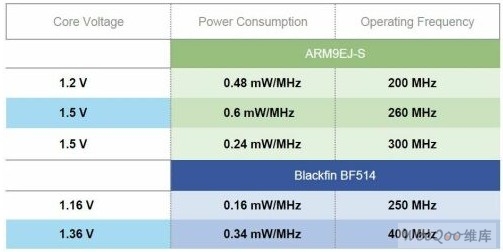
Figure 2: Comparison of operating voltage, operating frequency and power consumption of the two cores.
Ideal for multiple applications
BF51x is a new low-cost entry point in the Blackfin processor family. This series of products achieves a balance of performance, peripheral integration and price, and is very suitable for cost-sensitive applications, including portable test equipment, VoIP, industrial and instrumentation equipment.
The feature-rich BF51x provides an optimized low-cost product platform for VoIP, speeds up customer development of VoIP products, and can meet different market needs: 10/100 eMAC features help products achieve low BOM costs; powerful processors up to 400MHz Performance can meet the needs of product function expansion, add multiple channels and extended features (such as IP fax) without changing hardware conditions; you can directly use Global IP SoluTIons' VoIP package VoiceEngine for Blackfin processors to accelerate product design, GIPS VoiceEngine Media processing function can meet the most stringent requirements of VoIP equipment manufacturers; single-frame BF51x processor can perform system debugging and deployment more quickly in a unified software development environment, saving overall system cost; can be provided to run on uClinux operating system VoIP reference platform.
The BF514, BF516 and BF518 all have on-chip removable storage interfaces, which further expands the convergent processor series into portable applications. All three devices have: Secure Digital Input Output (SDIO) interface for connecting to standard flash memory and Wi-Fi cards; power-optimized CE-ATA storage interface for small handheld and consumer electronics applications; embedding Multimedia card (eMMC) interface, used to integrate large-capacity flash memory in various consumer electronics, wireless, navigation equipment.
For industrial control and test and measurement applications, Ethernet (IEEE1588 and 802.3) / wireless connections enable ease of use, simple connections for high-quality measurements, system programmable flexibility, and transfer from 8/16 to 32-bit solutions Has become an inevitable trend. The various features integrated in BF51x are in response to this development trend, bringing more convenience and available resources for engineers' design: BF516 added Ethernet with Media Independent Interface (MII) and Simplified Media Independent Interface (RMII) 10/100 MAC; IEEE1588 eMAC is used for Ethernet precision clock synchronization and network connection; three-phase PWM waveform generator for AC induction motor or permanent magnet synchronous motor control, and orthogonal interface for rotary encoder.
In addition, BF51x also has advantages in applications such as power equipment, embedded modems, biometrics, and motor control. Taking the design of power secondary equipment as an example, especially in low- and medium-voltage equipment, BF51x has a rich interface and excellent processing control capabilities, which can realize a single-chip solution, thereby saving equipment costs and shortening the development cycle.
When selecting a processor for the core hardware platform, the available design resources (including development tools and software library resources) are also important considerations, because this will determine the difficulty of product development and speed to market. BF51x can use the industry-leading tools and starter kits provided by the Blackfin processor family, including ADI CROSSCORE software and hardware tools and VisualDSP ++ integrated development and debugging environment (IDDE), emulators, and EZ-KIT Lite * estimated hardware. In addition, a large number of software modules such as VoiceEngine provided by third-party partners of ADI, as well as software library resources developed by ADI itself, can effectively help customers use BF51x processors to launch product designs with low cost and high efficiency.
What PCB designer Must Know About Impedance Control PCB
Controlled Impedance PCB Meaning
Impedance control has been one of the essential concerns and tough problems in high-speed PCB design. Impedance is the sum of the resistance and reactance of an electrical circuit. The resistance being the opposition to current flow present in all materials. In high frequency applications, controlled impedance helps us ensure that signals are not degraded as they route around a PCB. Resistance and reactance of an electrical circuit have a major impact on functionality, as certain processes must be completed before others to ensure proper operation.

Because of complex processors, USB devices and antennas are printed directly on the circuit board surface. The speed of signal switching on the circuit board increases, and the electrical characteristics of the tracks that transmit signals between devices become more and more important. Therefore, more and more PCB designs need impedance control and testing.
Impedance control technologies are quite important in high-speed digital circuit design in which effective methods must be adopted to ensure the excellent performance of high-speed PCB. The impedance of a PCB is largely determined by some factors, such as trace width, copper thickness, dielectric thickness, dielectric constant. Impedance, generally measured in Ohms. We must control the resistance and reactance of an electrical circuit to ensure the quality of signal in the complex design. For example single-ended impedance 50 ohm ±10%, differential impedance 100ohm ±10%.
When to Use Controlled Impedance
When a signal must have a particular impedance in order to function properly, controlled impedance should be used. In high frequency applications matching the impedance of PCB traces is important in maintaining data integrity and signal clarity. If the impedance of the PCB trace connecting two components does not match the components` characteristic impedance, there may be increased switching times within the device or the circuit. There may also be random errors.
Please note that we also need special instructions here:In DC circuits there is no reactance and the resistance of copper conductors is typically insignificant. However in high speed AC circuits (those with sharp changes in voltage and/or current) the reactance and thus the impedance can become very significant. This can become critical to a design's functionality because of the effects that changes in the impedance along the signals path from transmitter to receiver will have on the efficiency of power transfer as well as signal integrity. While a circuit`s speed is often expressed as the frequency of the wave form: the critical concern is the speed at which the voltage and/or current is required to change.
What Determines Controlled Impedance?
The characteristic impedance of a PCB trace is typically determined by its inductive and capacitive reactance, resistance, and conductance. These factors are a function of the physical dimensions of the trace, the dielectric constant of the PCB substrate material, and dielectric thickness. Typically PCB trace impedance can range from 25 to 125 ohms. The impedance value generated from the PCB structure will be determined by the following factors:
– Width and thickness of the copper signal trace (top and bottom)
– Thickness of the core or prepreg material on either side of the copper trace
– Dielectric constant of the core and prepreg material
– Distance from other copper features
Impedance Control In PCB Design

Electrical Impedance: A measure of opposition to time-varying electric current in an electric circuit.
The Problem: "A", "B" and "C" signals all reach the component at the same time.
The Solution: Apply Impedance to Circuit "C" to slow the signal enough for the component to first calculate ("A"+B").
Similar with a cable, the signal encounters a change of impedance arising from a change in material or geometry. Part of the signal will be reflected and part transmitted. These reflections are likely to cause aberrations on the signal which may degrade circuit performance (e.g. low gain, noise and random errors). In practice, board designers will specify impedance values and tolerances for board traces and rely on the PCB manufacturer to conform to the specification.
When rise times continue to reduce, inevitability the number of traces requiring impedance control will continue to increase. Where impedance control is needed it is important to control it accurately, calculating it with the most representative cross-section we can create.
Applications of Controlled Impedance
Controlled Impedance should be considered for PCBs used in fast digital applications such as:
– Telecommunications
– Computing 100MHz and above
– High Quality Analog Video
– Signal Processing
– RF Communication
Impedance Control PCB Manufacturing
In order to meet the growing demand of impedance control PCB, PCB manufacturers have invested a lot of money and manpower and material resources in production technology, in order to meet the production requirements of customers.
Due to the difficulty of impedance control PCB production, PCB manufacturers generally require PCB designers or purchasers to provide more detailed information and requirements, such as the type of material required, copper weight and thickness of the board, the number of layers, gerber file, so that the manufacturer can prepare the bill of materials (BOM). Impedance information should be clearly marked in Gerber file. If the necessary information is lacking, even a little key information will make it difficult or impossible for the manufacturer's engineers to know exactly what the customer needs.
Impedance-controlled PCBs are also divided into three different situations:
No Impedance Control: This is a situation where you do not need any extra design elements to ensure correct impedance because you have very loose impedance tolerance. Naturally, this will result in a faster-completed, less expensive board because the manufacturer does not have to include any special measures.
Impedance Watching: What is impedance watching? This is a situation where the designer will outline the impedance control trace and the PCB provider adjusts the trace width and dielectric height accordingly. Once the manufacturer approves these specifications, they can begin to manufacture the board. You can request a Time Domain Reflectometry (TDR) test to confirm the impedance for a fee.
Impedance Control: Actual impedance control is something you will typically only request when your design has tight impedance tolerances that could be tough to hit the first time around. When the capability limits of the manufacturer get close to the dimension requirements, it can be tough to ensure target impedance on the initial attempt.
In the case of impedance control, the manufacturer makes the circuit board achieve the target impedance as far as possible. Then they tested TDR to see if they succeeded. If not, they adjust accordingly and try again until they reach the required impedance.
Impedance Control PCB Fabricator
Impedance Control PCB is too complicated? No worry! JHY PCB engineers can help you at any time as we have three shifts. Free stack-up and impedance calculations can be offered upon request. We will work with your engineering team at the conceptual level of the PCB design to assist you to get better results in controlling impedance by choosing the suitable laminate and layer stack up.
Why Impedance Control PCB can be shipped timely all the time? As common materials are stored well in JHY PCB warehouse regularly. We have heavy copper thickness, 2oz, 3oz or more. Odd copper thickness H/1 oz, H/2 oz, 1/2 oz. Foil: 1/4 oz, H oz, 1 oz, 2 oz, 3 oz.
If you need order Impedance Control PCB, just make notes in Readme file, and send it together with Gerber, our engineer will take care of it. Have a try!
Impedance Control PCB
Blank PCB Board,Impedance Control PCB,circuit board prices,PCB With Impedance Control
JingHongYi PCB (HK) Co., Limited , https://www.pcbjhy.com