1 Overview
In order to save energy and reduce urban pollution, in winter, full use of the waste heat of the thermal power plant steam turbine after power generation can centrally supply heat to northern cities. The process of this kind of heating is that the hot water sent from the power plant to the heat exchange station in the city passes through the heat exchanger, and the temperature of the hot water in the primary water supply drops from about 90 to 60, and then flows back. power plant. The hot water sent to the homes of urban residents flows through the heat exchangers of each user, exchanges heat in the heat exchangers, and then flows back to the heat exchange station. The temperature of the secondary return water entering the heat exchanger of the heat exchange station is about 50%. , The secondary water supply temperature is about 60%. At present, there are many such heat exchange stations. Most of the heat exchange station equipment is relatively simple. It is generally composed of several heat exchangers, several pumps, a circulating pump group and a make-up pump.
The circulation pumps and make-up pumps of these heat exchange stations use manual opening and closing valves to control the flow, so the damping of the pipeline is increased, which results in wasted electric energy. With the development of frequency conversion technology, the use of frequency converters to retrofit old heat exchange stations to achieve automatic control has been accepted by more and more heating centers.
2 Frequency conversion speed control of heat exchange station
For example, a heat exchange station is composed of 4 heat exchangers, 4 37 kW pipeline pumps, and 1 3.7 kW make-up pump.
Shaanxi Baoji Thermal Power Co., Ltd. implemented an automated transformation of the heat exchange station from 2003 to 2004. The circulation pump and the make-up pump were adjusted by frequency conversion. The entire heating system was monitored by a computer, and the heat exchange station was unattended.
2.1 Frequency control of water pump
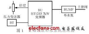
During heating, hot water runs in the heating system through the circulation pump. Leakage of pipes and valves will cause the water pressure of the circulating water to decrease. If the water is not supplied in time, the heating system will not operate normally. The frequency conversion pump replenishment method of the makeup water pump is relatively simple. The water pressure of the hot water in the system is set to 0.4 MPa. The pressure transmitter is installed on the return water main pipe. The pressure change on the pipe network is converted to 4 Yao 20 by the pressure transmitter. The mA signal is fed back to the input of the PI regulator of the inverter. The reference value of the inverter is set to 4 kg. When the pressure of the heating system is lower than 4 kg, the output frequency of the inverter rises to start replenishing water; when it reaches 4 kg, the feedback signal is basically equal to the given signal, and the output frequency of the inverter falls to stop replenishing water. In this example, one Senlan inverter BT12S3.7kW is used, and the pressure transmitter is Sennas DG130WBZ-A 1MPa. The frequency conversion water supply system is shown in Figure 1.
2.2 Frequency conversion speed control of circulating pump
Compared with the control of the make-up pump, the control of the circulation pump is more complicated. The ultimate goal of the heating system is to keep the indoor temperature of the thermal user stable, but because the thermal user does not have a room temperature regulator, and it is impossible to form a closed-loop control for the room temperature of many thermal users. In order to achieve economic operation and ensure the quality of heating, the most effective method is to control the secondary water supply temperature of the heat exchange station. Under steady-state conditions, the secondary water supply temperature under steady-state conditions can be obtained according to the law that the heat supply of the system, the heat dissipation of the radiator and the heat consumption of users are equal.
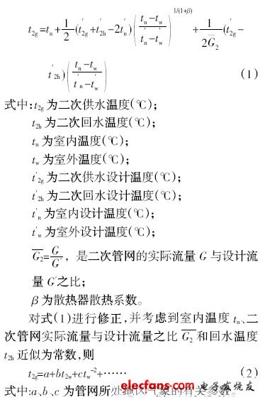
Equation (2) is the calculation method of the given value of the secondary water supply temperature. The t2g determined by equation (2) can track the change of the outdoor temperature tw, so that the indoor temperature of the hot user is not affected by the change of tw, and finally achieve stable heating.
Since the indoor heating system of the heat user adopts the single-tube heating method of top supply and bottom return, from the heating theory, the best adjustment method of single tube heating should be the comprehensive adjustment of temperature and flow. It can be seen from equation (1) that with the change of outdoor temperature tw, not only the secondary water supply temperature t2g must be adjusted in time, but also the flow rate G of the circulating water should be adjusted accordingly to avoid the occurrence of severely high room temperature in the upper part and severely low room temperature The phenomenon of "vertical imbalance". The water temperature of the secondary water supply is related to the temperature and flow rate of the primary water supply, the secondary return water flow rate, and the ambient temperature. Generally speaking, among these factors, the temperature and flow rate of the primary water supply are not adjusted at the heat exchange station, and the flow rate G of the circulating water can be adjusted. The control strategy of the secondary water supply temperature automation system is that if the secondary water supply temperature is low, the circulating water flow rate G increases; conversely, if the secondary water supply temperature is high, the circulating water flow rate G decreases. However, the influence of environmental temperature changes is not considered here. If the outdoor temperature changes, the indoor temperature should be basically constant. One control strategy is to use the temperature difference between the secondary inlet and return water to control the speed of the circulating pump inverter. The temperature difference between the secondary and return water is 12 benefits. When the temperature difference between the secondary inlet and return water jumps by 12%, the circulating pump inverter accelerates, and the flow rate G of the circulating water increases; when the temperature difference between the secondary inlet and return water is about 12 benefits, the inverter of the circulation pump decelerates The water flow G is reduced. Consider again that when the flow rate G of the circulating water is small, the rotation speed of the circulating pump is low, and the circulating water cannot be supplied to the user at the highest level. Therefore, based on the temperature difference control, the target value of the temperature difference can be appropriately adjusted within a certain range according to the minimum head required by the height of the thermal user. The control signal of frequency converter speed regulation is given by the automation system. Diagram of frequency conversion speed regulation system of circulating pump is shown in Figure 2.
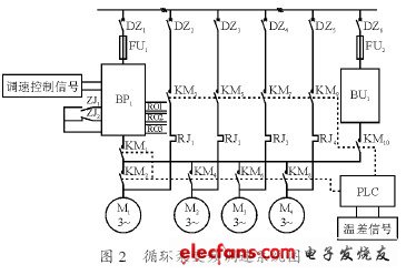
In the picture, BP1 is Senlan BT12S37kW inverter, BU is soft starter (automatic decompression starter), the system adopts cyclic switching mode, the temperature difference signal is sent to PLC, after PLC processing, to the inverter as speed control signal. When the system starts, the motor M1 frequency conversion speed regulation, when the frequency rises to 50 Hz, the circulating water flow does not meet the given requirements, then the motor M1 is put into industrial frequency, and M2 frequency conversion operation; if the circulating water flow still does not meet the given requirements, Then the motor M2 is put into industrial frequency, and M3 is operated with frequency conversion ... For some reason, the circulating water flow exceeds the given requirements, then stop the motor M1, M2 ... At any time, only one circulating pump motor is running with frequency conversion. If only one motor M3 is running with frequency conversion, and the circulating water flow does not meet the given requirements, the motor M3 is put into industrial frequency and M4 frequency conversion operation; M4 is put into industrial frequency and M1 frequency conversion operation, and it has reached the initial state. Motors M1 ~ M4 always switch between power frequency and frequency conversion. BU1 is used for backup, and the running information of the entire system is sent to the computer by PLC.
Rice Mill,Rice Mill Machine,Small Rice Milling Machine,Rice Mill Equipment
Hunan Furui Mechanical and Electrical Equipment Manufacturing Co., Ltd. , https://www.thresher.nl