1 Introduction
With the development of lighting technology, high-power white LEDs will be the core of future lighting. As a new type of light source, white light LED has the advantages of long life, small size, energy saving, high efficiency, fast response, shock resistance and pollution-free. It is considered to be a “green lighting source†that can enter the general lighting field, especially The birth of high-power white LEDs is called "the fourth revolution in the field of lighting" by the industry. The large-scale application of LEDs to general lighting is an inevitable trend [1 ~ 3].
The LED industry chain is generally divided into upper, middle and lower reaches, which are LED epitaxial wafers, LED packages and LED products. Among them, LED packaging, especially high-power LED packaging can no longer follow the traditional design concept and production mode (the traditional high-power LED packaging technology has some shortcomings, such as heat dissipation, light extraction, etc.) [4 ~ 6]. High-power LED packages are not only complicated in structure and process, but also have certain requirements on packaging materials. Therefore, it is necessary to study the traditional packaging process. Now we are faced with the challenge of finding packaging materials with excellent thermal conductivity; optimizing the package structure; and improving the packaging process.
With the development of lighting technology, in order to meet the requirements of general lighting, high-power chips are born, which puts higher requirements on the thermal, electrical and mechanical aspects of LED packaging. Traditional low-power LED packaging structures and processes are difficult to meet the requirements. .
2 Key Technologies for High Power LED Packaging
Compared to ordinary white LEDs, high power LED chips have a large heat flow rate that generates a large amount of heat. The research found that the luminous flux of the LED device is related to the package design of the chip's light extraction mode and light extraction efficiency, so the LED packaging method will develop in the following directions.
2. 1 low thermal resistance packaging process
Traditional lighting does not require high heat dissipation. Incandescent lamps and fluorescent lamps can radiate heat. White LEDs dissipate heat by heat conduction. LEDs are made of solid semiconductor chips as luminescent materials and use electroluminescence, so only a small part of the heat is emitted by radiation [7]. For existing LED devices, about 80% of the input power is converted into thermal energy, so chip thermal management is significant for LED packaging. Thermal management of the chip mainly includes the position of the chip, packaging materials (heat dissipation substrate, thermal interface material), package structure (such as thermal interface) and heat sink design.
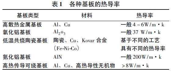
LED package has two main thermal resistances: internal thermal resistance and interface thermal resistance, and thermal resistance of the package material to heat the substrate. The heat generated by the chip is absorbed by the heat sink substrate and transmitted to the heat sink, and heat exchange with the outside is performed by the heat sink. Common types of LED heat sinks are: (1) High heat dissipation metal substrate: It has the advantages of high thermal conductivity, high heat resistance and electromagnetic shielding. However, the metal substrate has the disadvantage that the coefficient of thermal expansion of the metal is large. (2) Ceramic substrates have better heat dissipation properties, high temperature resistance, and moisture resistance. However, since the price is several times that of ordinary substrates, it has not yet become an ideal material for heat-dissipating substrates. (3) High heat conduction can be wound around the substrate and the same as the traditional rewritable substrate. In the case of the insulating layer, the soft epoxy resin is used to fill the high thermal conductivity inorganic material, which has the advantages of softness and high reliability [8]. The thermal conductivity of the above substrate is shown in Table 1:
2. 2 flip chip packaging technology
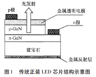
Conventional LEDs have a formal structure with a layer of epoxy resin on top and sapphire on the underside. In the traditional dressing LED chip package method, since P-type GaN doping is very difficult, most of the methods are now to prepare a metal transparent electrode on P-type GaN (see Fig. 1), so that the current is stably diffused to achieve uniform illumination. purpose. The PN junction of the prefabricated structure is dissipated through the sapphire substrate. Due to the poor thermal conductivity of the epoxy resin, the sapphire is a poor conductor of heat, and the thermal resistance is large, so that the heat conduction is not allowed, thereby affecting the normal operation of each device. .
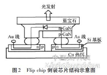
In order to overcome the shortcomings of traditional dressing LED chips, advanced flip chip technology is used to make two gold ball solder joints under the P and N poles of the chip (Figure 2). As the lead-out mechanism of the electrode, the gold wire is used to connect the outside of the chip and the Si substrate. This overcomes the drawbacks of the problem of light output efficiency and current of the positively mounted chip. The heat from the PN pole of the chip is transferred to the Si heat sink through the gold ball solder joint. Si is a good conductor for heat dissipation, and its heat dissipation effect is much better than that of sapphire. The use of flip-chip packaging technology not only improves the life of the LED, but also makes the LED's overall thermal performance a leap.
2. 3 Thermal Packaging Technology
The ability to successfully solve the heat dissipation problem has a great impact on the luminous efficiency and reliability of high-power white LEDs. For a single LED, the heat is all from the chip, and the size of the chip is very small. The heat cannot be dissipated in time, which will accelerate the aging of the chip and the phosphor. It can also cause the solder of the flip-chip solder to melt and the chip to fail. When the temperature exceeds a certain value, the failure rate of the device changes exponentially. The data shows: For every 2 °C rise in component temperature, the reliability is reduced by 10%. In order to ensure the life of the device, the temperature of the PN pole is generally required to be below 110 °C, so the heat dissipation of the chip is a problem that must be solved by the LED package [11]. There are two ways to solve the heat problem: First, improve the quantum efficiency of the chip, that is, improve the luminous efficiency of the chip, and fundamentally reduce the generation of heat; Second, the improvement of the LED structure, the internal heat is accelerated, and the chip is effectively reduced. Temperature [12].
The influence of the package interface on the thermal resistance is also very large. If the interface is not handled correctly, it is difficult to obtain a good heat dissipation effect. Improves the gap between the key interfaces of the LED package and enhances heat dissipation. Therefore, it is very important to select the material of the chip and the heat dissipation substrate. The commonly used packaging material for the LED is a thermal conductive adhesive, and the thermal conductivity is very low, so that the interface thermal resistance is high. The low temperature solder paste is used as the thermal interface material, and the interface thermal resistance is greatly reduced. In order to achieve better heat dissipation, a new die-bonding process, namely eutectic soldering technology, is introduced, in which Si wafer bonding is used as a connection material between the heat sink and the die (structure is shown in Figure 3). The heat dissipation effect and physical properties are far. It is better than Ag glue used in the past (Ag glue has high thermal resistance, and Ag glue is equivalent to artificially adding a layer of thermal resistance between the chip and the heat sink), and has achieved good thermal conductivity.