Introduction of SWR5800 Broadband Wireless Access System
I. Overview
SWR5800 OFDM broadband wireless access system is the latest IP-based point-to-multipoint fixed broadband wireless access system launched by Sunet. It works in the 5.725-5.850GHz wireless microwave frequency band and uses OFDM orthogonal frequency division multiplexing technology. The all-weather coverage of the base station is 5-10 kilometers, which can provide high-speed Internet data, image and IP voice transmission services. SWR5800 OFDM broadband wireless access system adopts OFDM orthogonal frequency division multiplexing technology, effectively solves the problem of multipath effect interference, supports close-range non-line-of-sight data transmission (NLOS), has advanced technology, high reliability, and strong scalability With the advantages of high cost performance, it is suitable for the needs of domestic telecommunications operation technology, and is an ideal solution for operating wireless networking in the mall domain.
Based on OFDM orthogonal frequency division multiplexing technology SWR5800 system adopts OFDM orthogonal frequency division multiplexing technology to achieve orthogonal overlap of signal spectrum to obtain high spectrum utilization rate and maximize the use of available frequency bands. It is especially important for operators with limited frequency resources; OFDM technology has good frequency diversity and solves the multipath effect interference problem that plagues operators in conventional systems. The SWR5800 system has good anti-multipath interference capability, and the requirements for line-of-sight transmission are reduced. It can support non-line-of-sight (NLOS) transmission, and is particularly suitable for complex urban networking environments. Therefore, the SWR5800 system is particularly suitable for use in high-rise buildings, densely populated and geographically obstructed environments, and where it is desired to eliminate the effects of multiple channels and ensure high-speed data transmission.
Second, the technical advantages of SWR5800
SWR5800 series broadband wireless access equipment adopts advanced OFDM technology, which has the characteristics of high transmission rate, strong anti-interference ability, stable performance and high cost performance. Sunet wireless QOS system is an efficient base station bandwidth management system based on IP, which can provide efficient bandwidth management and flow control, can provide real IP and virtual IP for end station users, and can provide data and voice services for each IP at the same time, and Can fully guarantee the high quality of voice services. The wireless QOS system can simultaneously control and manage 8 sectors, provide 8-sector base station 208Mbps bandwidth service, and has perfect flow control and history records. SWR5800 broadband wireless access system is suitable for the characteristics of domestic telecommunications operation technology requirements, and is an ideal solution for the construction of broadband wireless metropolitan area networks.
Using OFDM (Orthogonal Frequency Division Multiplexing) technology: support non-line-of-sight transmission, NLOS strong anti-interference ability.
Large system capacity: the transmission data rate is up to 54Mbps, the actual air transmission rate can reach 30Mbps, when using 64QAM,
The capacity of the four-sector base station system can reach 216MHz bandwidth.
Long transmission distance: The typical application distance is 5-8 km, and the highest gain directional antenna can reach up to 30km.
Short construction period: rapid installation and deployment can be achieved by sector coverage.
IP-based QOS bandwidth management system: provides flexible and efficient bandwidth management and flow control functions, making full use of frequency resources.
Strong expandability: With the increase of users, equipment can be added at any time through the network management system to increase system capacity.
High cost performance: low equipment cost, reducing investment and operating costs, which is conducive to quick recovery of investment.
High reliability: advanced technology, stable performance, easy installation and maintenance.
3. Application field of SWR5800 system
Operators use mature 5.8GHz broadband wireless access technology, which can quickly and low-cost wireless coverage of large urban areas. The 5.8GHz point-to-multipoint wireless access system can be used alone or wirelessly connected to 2.4GHz and 3.5GHz Into the system hybrid networking, or as a supplement to wired access, covering areas where there is no wired network, carrying out Internet access and value-added services such as IP voice, VPN, video conferencing, VOD, etc., and making it the main wireless access Access means.

| 4. Types of services provided |
At present, the business projects that SWR5800 broadband wireless access system can provide can be divided into two parts: data and voice. Data section 1. High-speed Internet data access, while providing various data services based on IP networks; 2. VOD video on demand; 3. Video conference; 4. Video surveillance; 5. Broadband VPN service; 6. Internal connection, cross-regional connection and WAN connection in the enterprise network. Voice part IP voice call. |
| V. Network master plan |
According to the planning of broadband wireless access network construction and the requirements for system functions, and comprehensive consideration of the distribution, terrain and building layout of users and potential users in the planned network construction city, the construction of SWR5800 broadband wireless access system can be implemented separately It can also be used as a supplementary access method for 3.5GHz MMDS network. By selecting and setting up a 5.8 GHz central base station in an urban area, an 8-sector approach is used to omnidirectionally cover an area of ​​5-10 kilometers, and a 5.8 GHz broadband wireless access network is established. In order to supplement and backup each other with the 3.5GHz MMDS network and strengthen the network coverage, the location of the 5.8GHz central base station can be co-located with 3.5GHz. The base station consists of one or more access points (APs). The system uses 45 ° antennas. The half-power beam of each AP antenna is 45 ° × 16 °, forming a 45 ° sector in the horizontal direction. The base station can cover multiple users in a 360 ° radius through 8 sectors, and each sector can access up to 253 remote stations. Multiple APs in the same central base station use different frequencies and polarizations to cover multiple directions to improve spectrum utilization and increase the access bandwidth of the central base station. The purpose of using sector antennas is to provide a wide coverage and powerful transmission capabilities. End station users can use directional antennas to point to the sector antennas used by the base station to ensure data transmission from the base station to the terminal station. According to the distance between the terminal station and the base station, the terminal station can select antennas with different gains to enhance the signal strength. Between base stations, 5.8GHz equipment can be used to connect, reducing construction costs and providing high-efficiency data communication between base stations (HE). Each central base station is managed by a control server (CS) for the entire central base station, and the access points, the control server and the broadband network are connected by Ethernet switches. The terminal station and the base station communicate wirelessly, and connect to the local LAN through the 100 / 10Base-T Ethernet interface. Each user can share bandwidth with other users via an Ethernet switch or router to improve the efficiency of the entire network. At the same time, it is easier to deploy in the network. The network management system can store user data and system configuration, perform fault diagnosis, alarm, and statistics on the entire system, communicate with the control server of each central base station through the IP protocol, and system administrators control, maintain, and set up through the management terminal. Each city gradually establishes 10 base stations: each base station uses a 45 ° sector antenna, each sector provides 4 remote station users, There are 8 antennas in total, covering a range of about 5 to 10 kilometers. Each city gradually establishes 320 terminal stations: each base station has 8 sectors, and each sector develops 4 users. Therefore, each base station There are 32 users in total, and 10 HEs have 320 users. In the scheme, we will use SWR5800 series broadband wireless access equipment to do point-to-multipoint wireless network on the roof of the building Erection work, the system is safe and reliable, and the economic benefit ratio is high. The equipment uses OFDM orthogonal frequency division multiplexing technology, and the data transmission rate can reach 54Mbps. The base station uses 8 SWR5800 AP external flat panel antennas to connect with the SWR5800 RU, which can achieve 360-degree seamless coverage Cover, and ensure the bandwidth of the network, and can provide IP voice, video conferencing system, multimedia data transmission, VPN virtual Various value-added services such as private network and VOD video on demand. In the case of remote stations using directional antennas, the longest transmission distance can reach 20 kilometers. The antenna directions are aligned, and a coaxial lightning arrester is installed between the antenna feeder at each point and the outdoor unit. The power supply mode of Ethernet network cable can be used, which is convenient for installation and erection, and is also conducive to future maintenance of the equipment. |
6. Network topology |
The overall structure of the 5.8GHz wireless access network is divided into three layers, namely the backbone layer, the convergence layer and the access layer. Among them, high-end router equipment is used to connect to the Internet at the backbone layer. At the aggregation layer, Ethernet switches and router devices are used for data exchange and aggregation. The basic backbone network is realized by optical fiber or microwave transmission network, including ATM switching or IP switching or IP + ATM core switching platform and interconnection module with Internet and PSTN. The access layer is composed of wired and wireless parts. The entire network is a star structure. The wired part uses optical fiber links to provide high-quality connections from each base station to the central control room. The wireless access part uses the SWR5800 broadband wireless access system to provide The 10 / 100Baset interface connects routers and switches to carry out various data access services such as Internet, VPN, and VoIP. The backbone network generally concentrates a large amount of information transmission. The switches on the backbone must complete a large number of network transmission tasks while completing the transmission of VLANs across the backbone. Therefore, the backbone switches must be required to have high packet switching capabilities, and should comply with IEEE802 .1Q standard. Network core layer The network center is located in the network management center, and a network sub-center is set up in places such as wireless network base stations. The center and the sub-center are connected into a star structure. A central switch is placed in each branch center. The system will select the network equipment with strong processing capacity, reliability and high stability as the central switch of the system. After dividing the subnets, it will provide a guarantee for stable communication between the network sub-centers. The switch uses dual power supplies to provide redundant configurations. In order to ensure high stability and reliability of the system, it is recommended to use a high-performance Layer 3 switch Cisco 6509 as the central switch of the backbone network in the information center. Network aggregation layer This system sets up 3 sub-centers, that is, 3 aggregation centers. The aggregation layer realizes the connection with the core layer and the wireless access network, provides upstream and downstream data channels, and configures secondary switches. Cisco 3550 switches are recommended. router According to demand, current application and future development, it is recommended to choose CISCO's 7200 router, which supports 1000Mbps routing interface and multiple business interfaces to provide channels for remote connections and other operators.
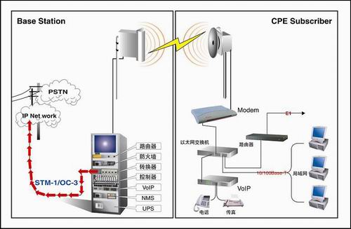
5. Network connection diagram of 8GHz fixed wireless access system |
Seven, SWR5800 system composition |
The composition of SWR5800 broadband wireless access system and equipment is as follows: |
SWR5800 system and equipment composition |
SWR5800 broadband wireless access system is composed of two parts: base station and terminal station. Base station configuration equipment includes: outdoor radio frequency unit (ODU), indoor unit (IDU), router, switch, firewall, VOIP Voice gateway, wireless QOS system and UPS power system. The radio frequency signal is received from the sector antenna, first transmitted to the wireless QOS system, then transmitted to the Ethernet switch, through the Ethernet The network switch reaches the destination. The base station can connect to the ATM backbone through ATM-to-Ethernet switch equipment. In the terminal station part, the outdoor radio frequency unit can realize multi-user access through the Ethernet switch. The VOIP voice gateway is connected to the Ethernet switch to provide IP voice telephone service. The network interface of SWR5800 terminal station and base station equipment is a standard 10 / 100Mbps Ethernet interface. It can be connected to a single user terminal. Because it provides a standard 10 / 100Mbps Ethernet interface, it can also be connected to the user's office. The LAN connection provides broadband data access directly to the user's LAN. The user's LAN can be the user's corporate network or The private network fully embodies the flexibility of the SWR5800 system. 8. IP Phone Solution Using the above-mentioned metro broadband wireless access network as a transmission medium, H.323 technology is used to transmit voice packets to a remote station, and an IP telephone billing system is provided for future commercial applications such as "IP telephone supermarket". This IP telephone service system converts voice or fax to data through a VOIP voice gateway, and then shares the same with the data IP network. Since voice and fax are transmitted on the data network, it is free to communicate with each other and send and receive faxes within the network. The line QOS system can provide a bandwidth management mechanism, which can manage the bandwidth of 8 sectors of 208Mbps. Based on IP (IP Base) Way to provide voice and data transmission services to each user. Real-time traffic monitoring service can be performed in the computer room at the central base station, And can provide up to 18 months of historical traffic records. Sunet's VOIP voice gateway has a built-in QOS mechanism, which allows voice packets to take priority over data packets to fully ensure voice over IP communication. Voice quality, and can be used in conjunction with the wireless QOS system, so that voice quality reaches carrier-grade standards. The system has strong expansibility, can flexibly combine various ports, and the devices can be stacked in series to facilitate system expansion. |
1.Shape:Conical ,Multi-pyramidal,Columniform,polygonal or conical
2.Material:steel plate.stainless steel compound plate,stainless steel plate,ect.(anticorrosion treatment with hot galvanization,also color polyester power could be coated on the surface)
High strength low alloy steel Q235,Q345,GR65,GR50 to ensure the mechanical properity of microelement in order to ensure the quality of galvanization (other materials are also avaliable on request)
3.Jointing of pole with insert mode,innerflange mode,face to face joint mode
4.Design of pole :against earthquake of 8 grade ,aganist wind pressure of 160
5.Minimum yield strength:355 mpa
6.Minimum ultimate tensile strength :490 mpa
7.Max ultimate tensilestrength:620 mpa
8.Certificate:ISO9001-2000
9.Length:Within 14m once forming without slip joint
10.Welding:It has past flaw testing.Internal and external double welding makes the welding beautiful in shape
11:Packages:Our poles as normal cover by Mat or straw bale at the top and bottom ,anyway also can following by client required , each 40HC or OT can loading how many pcs will calculation base on the client actually specification and data
Our lighting equipment are made from quality sheet from bending,forming,automatic welding and hot galvanization.We can reach one-run machining length of 14m,and can bend sheet thickness up to 25mm.We adopt advanced welding procedures ,automatically weld main joints and reach rank-II welding quality.

Galvanized Steel Pole,Galvanized Steel Electric Pole,Monopole Galvanized Steel Electric Pole,Galvanized Steel Street Lighting Poles
YIXING FUTAO METAL STRUCTURAL UNIT CO.,LTD( YIXING HONGSHENGYUAN ELECTRIC POWER FACILITIES CO.,LTD.) , http://www.chinasteelpole.com