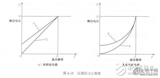
In Figure 4-15, curve 1 represents the U/f characteristic of the motor when low-frequency compensation is applied while driving the LXT905LC dynamic constant torque load. Curve 2 shows the U/f characteristic without low-frequency compensation under the same constant torque load condition. Curve 3 illustrates the U/f curve with low-frequency compensation when the motor is driving a water pump fan load, and curve 4 depicts the U/f curve without low-frequency compensation for the same type of load. These curves demonstrate how different load types affect the voltage-to-frequency relationship during motor operation.
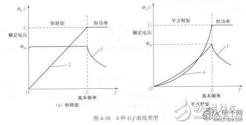
As shown in Figure 4-15, it is also evident that once the motor reaches its rated voltage, the inverter cannot increase the output voltage beyond this point. Therefore, above the base frequency (f_i), the output voltage (U) remains at the rated level, resulting in a horizontal line on the U/f curve. This change affects the magnetic flux according to equation (4-4). As the frequency increases, the magnetic flux decreases, leading to reduced torque. Consequently, the motor transitions into a constant power speed control mode. For example, when maintaining a constant voltage (U = fixed value), the magnetic flux variation is more pronounced, as illustrated in Figure 4-16.

In Figure 4-16, curve 2 represents the U/f characteristic without low-frequency compensation when the motor is driving a constant torque load, while curve 1 shows the corresponding flux variation. Below the base frequency (f_i), the flux remains constant, which corresponds to the constant torque speed control mode. However, when the frequency exceeds f_i, the flux decreases, and the flux variation follows an inverse relationship, representing the constant power speed control mode. Curve 4 illustrates the U/f curve without low-frequency compensation when the motor is driving a square torque load, and curve 3 reflects the corresponding flux variation. Below f_i, this corresponds to the square torque speed control mode, while above f_i, the flux again follows an inverse relationship, indicating constant power speed regulation.

Tin Zinc Antimony Copper Alloy Wire
It was made by Tin,Zinc, Antimony and Copper,Have a good metal characteristics.
SZSC is an alloy wire with Sn-Zn-Sb-Cu,Aproper amount of improvement elements are added to the tin zinc based alloy to inhibit oxidability. Various studies show that the current speed can be reduced.improve the performance of the alloy and wire is wildly applied with high cost performance.
In past 20 years,Our company make a various of SZSC prodouct,SZSC-1,SZSC-2A,SZSC-2B,SZSC-3, SZSC-4, SZSC-5, SZSC-6, SZSC-8.Can help the customer reduce the cost one by one.It is one of the best underlayer metal spraying materials for pure aluminum film.
Our product conforms to the requirements of EU ROHS,REACH and relevant domestic laws and regulations for environmental protection.
Copper Alloy Wire,Beryllium Copper Wire,Brass Wire,Tinned Copper Wire
Shaoxing Tianlong Tin Materials Co.,Ltd. , https://www.tianlongspray.com