Simple protection program for overvoltage automotive video drive circuit
Abstract: This circuit can prevent accidental contact with the car's video amplifier to the car's battery voltage (16V maximum), by inducing voltage failure, and quickly open the connection between the amplifier and the battery.
In a typical automotive video application, the video DAC (from the rear camera or DVD player, for example) is followed by a low-pass reconstruction filter and amplifier, and the video signal is transmitted to the LCD display. This amplifier and all similar automotive circuits must be protected and connected directly to the car's battery voltage. Since the car battery voltage ranges from 12V to 16V, the minimum protection required is 16V.
Figure 1 shows the output of a simple circuit-protected video filter amplifier to the battery (used by the MAX9502). The MAX9502 uses the following video DAC component costs and board space that are otherwise required to eliminate the passive low-pass reconstruction filter of the Legislative Council. In most applications, the ground reference current output of the video DAC, and the RX value (75Ω to 300Ω, depending on the characteristics of the video DAC) are set at 1VP-P video amplitude.

figure 1. The circuit is automatically protected by the overvoltage video driver at VOUT (used by the MAX9502) by turning off the transistor supply M1.
When the output voltage of the circuit (VOUT) exceeds 7V, the inverter output becomes low, and the money supply M1 turns off the transistor, thereby protecting its output MAX9502 using isolation. When the return of VOUT is lower than 7V, the inverter outputs a high level, enabling the money supply M1 to open and re-establish the video channel.
Figure 2 shows the transient response of the circuit in Figure 1. Since the voltage at VOUT rises from 0V to 16V, the money supply M1 of the transistor keeps TP_C low. The ESD protection diode is connected to the MAX9502 internal output from VCC. During this period, the clamp output (TP_D) is between 3.3V. This is because for a short time, the MAX9502 uses no damage and the power supply connected to its VCC pin is not affected.
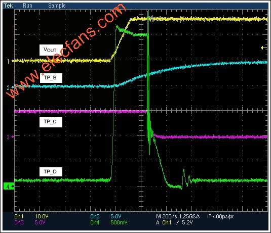
figure 2. Transient response waveform Figure 1 circuit.
Table 1 shows an appropriate termination resistance of 75Ω (Rx), measured with the Tektronix VM700 video setup to take overall video performance. The performance is good, and there is a negligible effect on the video quality with the transistor supply (M1).
The Solar Fan is made up of solar cells, wires, connectors, switches and dc electromechanical connections. Solar cells are powered by sunlight and drive the motor to run, turning the fan blades mounted on the motor shaft to create a cool breeze. Sunny, windy, low noise, safe and reliable. Is suitable for the place without electricity, such as booth, sentry box, family, tents, medical, barracks, and places without electricity, blowing cool, heat and cooling, solar electric fan, it includes solar battery, motor and fan blade, whose character is: the solar cell and sunshine vertical direction, the light electricity, to power a fan straight flow, through a wire, connectors, switches connected to the electric motor order. FIZZ GLOBAL offers solar roof fans, solar floor fans, solar ceiling fans, etc.
Solar Fan
Solar Fan,Solar Attic Fan,Solar Ceiling Fan,Solar Table Fan
ZHEJIANG FIZZ NEW ENERGY CO.,LTD , https://www.ywfizz.com