1 Introduction
This article refers to the address: http://
At present, automotive electronics is developing in the direction of networking, and the in-vehicle network has become the biggest hot spot in the field of automotive electronics. Key technologies in network bus applications that improve communication reliability between control units and reduce lead costs include CAN, LIN, FlexRey, MOST, IDB1394, and more. For automotive OEMs, CAN network design is the key to applying CAN network communication. Throughout the existing design techniques, they can be divided into two categories: one is the traditional design method based on simulation and testing; the other is based on the protocol design. The traditional method puts together the requirements of each node for the protocol, and verifies the correctness of the protocol through simulation and testing methods, and finally obtains the communication protocol. The new method uses the system design technology to model the timing of the system by theory, analyzes the communication protocol of the design system, ensures the real-time performance of the system and the correctness of the protocol, and finally releases the correct communication protocol. This article will briefly introduce the limitations of traditional design methods and the advantages of the new method, as well as the communication network software system designed with reference to the new method.
2 Limitations of traditional design methods
With the increasing number of electronic devices on the car, the in-vehicle network system is becoming more and more complex, and the automotive electronic network faces enormous challenges. The limitations of traditional network protocol design techniques are more and more prominent, mainly in three aspects: data loss, communication delay, and protocol modification difficulties.
2.1 Data loss
Data loss refers to the situation where new data has not been transmitted through the network or transmitted beyond the receiving time limit of the receiving node. Data loss can seriously affect the real-time performance of communication, which in turn affects the quality of vehicle communication. Systems with good real-time performance should completely avoid data loss.
The influencing factor of data loss is the communication protocol. The traditional design method detects the correctness of the protocol through simulation and testing. The disadvantage is that it cannot cover all the test cases. Therefore, the output communication protocol may have potential errors or is not complete, which will inevitably lead to data loss. , affecting the performance of the entire system.
2.2 Communication delay
The communication delay is the waiting time for the data to be ready to be sent out through the bus. Communication delays can lead to data loss, a fundamental problem that traditional design methods cannot solve. This is mainly because the traditional design method only puts together the requirements of each node for the protocol, and does not consider the requirements of the whole system. For example, the sending node sends data to the receiving node to receive data and is used for control, without considering the time requirement for implementing such a complete function. . Therefore, the protocol design results are difficult to guarantee real-time performance, and communication delay is inevitable.
Arbitration failure is the main cause of delay, so the delay is related to the ID and period of the message. The more complex the system, the more likely it is that there will be competition between messages, and the worse the real-time performance of the system.
In order to reduce the impact of delay, the traditional design approach takes two precautions. One is to set the time limit, as shown in Figure 1. Another limited load is about 30% on average, reducing the possibility of message contention. But neither of these methods can fundamentally eliminate the delay.
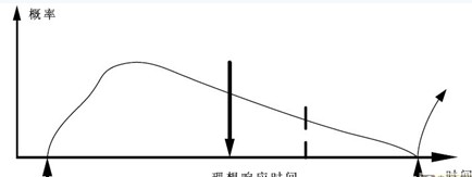
Figure 1 Calculation of time limit setting and response time
2.3 Agreement modification difficulties
Modifying the agreement is inevitable during the development process. However, for the traditional design method, because of the fusion of application and communication functions, the parameter changes of the communication protocol will lead to software recompilation and testing, which means additional time and cost, the supplier is very reluctant to modify the agreement of the vehicle manufacturer. . Therefore, it is very difficult for OEMs to modify the agreement and it will take a long time.
3 Characteristics of new methods based on protocol design
The protocol-based approach guarantees the accuracy of the communication protocol, avoids data loss, and ensures the real-time performance of the system through system-level design theories and methods. Its characteristics are summarized as follows:
3.1 System level design to avoid data loss
The new technology uses top-down system design techniques to design and optimize the entire system architecture. Through the theoretical design method, the correctness of the communication protocol can be guaranteed, and the data loss problem can be fundamentally solved.
3.2 Effective control message delay
The response time is the total time that the message is ready to be sent to the last node to receive the data. It is the sum of the transmission time and the delay. The delay is the main factor affecting the response time. The control delay can effectively control the response time.
As shown in Figure 1, the response time is modeled and the ID and period of the message are carefully scheduled to control latency, response time, and bus load. The worst case delay time, maximum response value, and bus load are then theoretically calculated.
Since the new method can calculate the maximum bus load and can effectively control the system delay, there is no need to impose any restrictions on the system bus load, which can theoretically reach 100%. The advantage is that it ensures a certain communication behavior and can effectively utilize system resources.
3.3 Separate applications and communication protocols to ensure change flexibility
As shown in Figure 2, the new method provides a standard network communication component for ECU communication functions. This component successfully separates the application and communication protocols so that their modifications do not affect each other, ensuring flexibility in protocol modification. The network communication component provides a standard interface to the bus, application and communication protocols. The application-oriented interface is a signal-based operation that does not include parameters for the communication protocol. The interface to the communication protocol is responsible for identifying the communication protocol. As long as the interface standard is adhered to, the protocol can be changed arbitrarily without affecting the application.
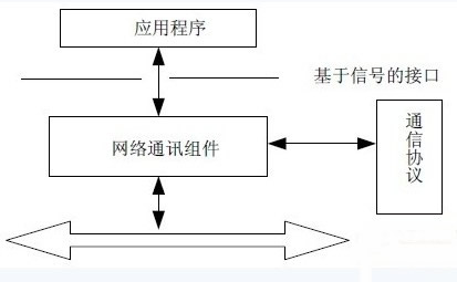
Figure 2 Separating applications and communication protocols
The advantage of this design is that the vehicle manufacturer can easily modify the protocol without vendor support, thus ensuring the flexibility of system changes, while also increasing the portability of the system and the reusability of the application.
4 system design
In order to avoid the shortcomings of the traditional design method, the system is designed with reference to the new method theory. The whole system is mainly divided into two parts: one, static configuration compilation tool; two, network components, called COM components.
4.1 Static Configuration Compilation Tools
The static configuration compilation tool uses a configuration language for configuration of signals, frames, frame modes, and the like. The configuration language defines the configuration rule syntax for four files: fixed file, network file, target file, and private file.
The .fix file is primarily used to describe the available network interfaces and a description of the signals sent and received by each communication interface in the ECU. These descriptions can be defined at an early stage of the project, even before the supplier is selected.
The .net file is usually created by the system Interator and is mainly used to describe the network interface configuration, signals, frames and their parameters (such as frame ID, transmission type, period, offset, and signal mapping table). In addition, it is also possible to define the schedule of the schedule (applicable to the case of using a gateway). This information will be stored in NVRAM and is not directly visible to the application.
The .tgt file is provided by the ECU's vendor and includes a description of the hardware characteristics of the ECU, such as the type of CPU, the size and address of the memory in which the data is stored, and so on.
The .pri file is mainly used to define the signal's flag, timeout, and signal renaming. By using the four files configured in the configuration language, the statically configurable configuration is realized, and the timing of signal transmission is controlled, the communication delay is effectively controlled, data loss is avoided, and network resources are fully utilized.
The four files obtained after configuration are compiled by the configuration compiler to generate three files: s_gen.c, s_hand.h, and s_nvram.
The s_gen.c file contains the data structures generated by some of the configurations, and these data structures are integrated and linked with other ECU application software code provided by the ECU vendor. The application software will include the s_hand.h file to access different communication objects, such as specific signals. The s_nvram file is the generated ECU binary configuration data.
4.2 COM components
The COM component adopts a hierarchical structure design method, which is mainly divided into: an InteractiON layer and a device driver layer. The interaction layer has a gateway function, which implements signal level routing.
The interaction layer in the COM component has the following functions: 1. Provide standard application-oriented signal interface; 2. Provide unified service for network management; 3. Provide unified service for diagnostic communication; 4. Hide protocol and information attributes from application; Provide data transmission between different networks; 6. Provide gateway function.
The driver layer in the COM component provides the following functions: 1. Sending data submitted from the interaction layer; 2. Receiving data from the CAN hardware and submitting it to the interaction layer; 3. Confirming the upper layer's transmission request, and reporting the confirmation information to the interaction layer; 4. Confirm the completion of the reception and report the confirmation information to the interaction layer.
Signal reception: When there is information in the underlying network, the CAN transceiver filters, and only the frames that meet the filtering conditions can be received by the CAN device through the driver layer. The driver layer then passes the received data to the interaction layer. The application obtains the corresponding signal in the eligible frame by a signal read operation.
Signal transmission: The application calls the signal write function to send the relevant signals to the interaction layer. The interaction layer passes the information to the driver layer by calling the output function for the output function. The driver layer calls the relevant send function to transfer the information to the CAN bus. The schematic process diagram is shown in Figure 3.
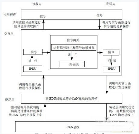
Figure 3 Signaling and receiving operations using COM components
5 Conclusion
The system designed in this paper adopts a new design principle, which separates the application and the agreement well, reduces the dependence of the vehicle manufacturer on the supplier, reduces the development cost and development cycle of the whole vehicle, and at the same time, as the vehicle developed independently by China. The network solution provides a certain theoretical basis for the progress of China's automotive electronics industry to a certain extent.
The author of this paper innovates: This network design adopts the system design method, which breaks through the traditional design method of patching together by simulation test, which enables the vehicle manufacturers to flexibly design and modify the protocol, greatly reducing the dependence on suppliers. Sex. At the same time, this design method also ensures the portability and reusability of the system, and increases the network usage.
The GFCI will not protect you from line contact hazards (i.e. a person holding two "hot" wires, a hot and a neutral wire in each hand, or contacting an overhead power line). However, it protects against the most common form of electrical shock hazard, the ground-fault. It also protects against fires, overheating, and destruction of wire insulation.
Ground Fault Circuit Interrupter UL
Ground Fault Circuit Interrupter UL,Auto-Monitoring Ground Fault Circuit Interrupters,Ground Fault Circuit Interrupter,Outlet Ground Fault Circuit Interrupter
Hoojet Electric Appliance Co.,Ltd , https://www.hoojetgfci.com