In recent years, lamps made with 1 to 3W high-power LEDs have increased year by year, and their power can range from a few watts to hundreds of watts. High-power LED lamps adopt the structure of LED series connection, and are powered by constant current. The structure is shown in Figure 1. Generally, the operating current of a 1W LED is 250-350 mA, the operating current of a 3W LED is 600-700 mA, and the current is 900-1000 mA.
Figure 1 LED drive circuit
Such a series LED lamp has a disadvantage that if one of the LEDs in series is open, the entire lamp is not illuminated. This is very dangerous for the application of certain lamps (such as warning lights, miner's lamps, emergency lights, etc.). In order to prevent the LED light from being bright when the LED is open, it is very effective to use the LED open circuit protector, which can ensure the safety of the lamp.
The 1W LED open circuit protector that has been developed has two structures: Zener diode type and thyristor type (one-way thyristor type), as shown in Figure 2. Some LED manufacturers directly package Zener diodes with LEDs , that is, LEDs with open circuit protection are also available. The operating current of the 3W LED is generally 700 to 1000 mA. This open circuit protector is still rare in the market due to the large current.
Figure 2 Two LED protection devices
This article will introduce the new device NUD4700 launched by ON Semiconductor in January 2009 and the SMD602 introduced by SMD in 2008. They are all thyristor type LED open circuit protectors.
How does the NUD4700 work?
The NUD4700 is a two-terminal device whose appearance is shown in Figure 3. The A terminal is the anode and the C terminal is the cathode. Its internal structure is shown in the lower diagram of Figure 2, which consists of a control circuit and a unidirectional thyristor.
Figure 3 NUD4700 shape
The typical application circuit of the NUD4700 is shown in Figure 4. This is an AC power supply that outputs DC voltage to the AC/DC converter, and the NUD4701 constant current LED driver drives five series of 1W high-power LEDs. The NUD4700 is connected in parallel with the LED. When the LED is not open, the NUD 4700 is in the "off state" because the forward voltage drop VF of the LED is less than the "on" voltage V(BR) of the thyristor.
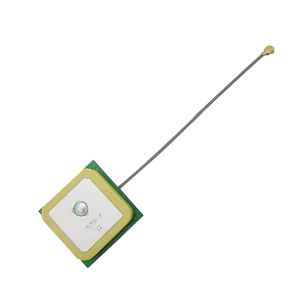
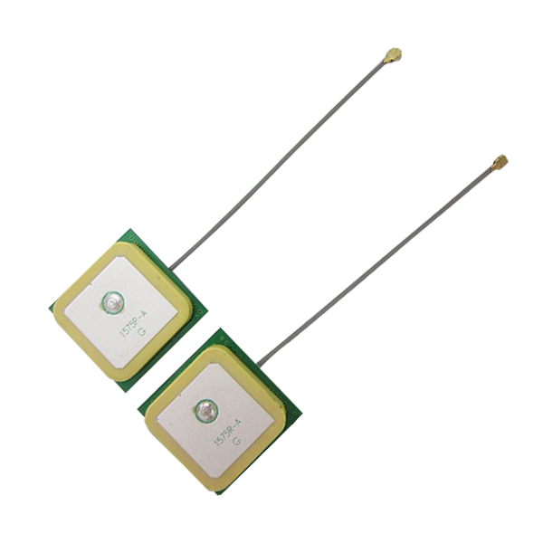
An internal active GPS Patch Antenna with cable is used in most mobile devices today that require high signal strength in a small form factor. It is the highest performing solution of all antenna types.
Usually consisting of a specially formulated dielectric ceramic, a trace is printed on the substrate to get the desired right hand circularly polarized Patch Antenna topology. The patch is mounted on a PCB; underneath the PCB is the Low Noise Amplifier (LNA) which amplifies the GPS signal before being transmitted through the coaxial cable and connector to the receiver.
This design application note is intended to help the antenna integrator understand the relevant parameters affecting the antenna performance.
Yetnorson recommends that the integrator strictly follow the guidelines in this application note. Upon your device prototype completion, Yetnorson can provide further optimization by offering custom tuning and testing services for the antenna in your device.
Gps Patch Antenna Description:
- Central frequency: 1575.42 MHz
- 8 cm cable
- Amplifier gain: 28dBi
- Connection: dip soldering
- Standing wave ratio: less than or equal to 1.5
- Impedance: 50ohm
- Noise coefficient: less than 2.0
- Dc voltage: 3 ~ 5V
- Dc current: 10 ma
Gps Patch Antenna Specification:
- Material: Metal + Plastic
- Size: Approx. 25*25*10 mm / 0.98*0.98*0.39 inch
Gps Patch Antenna Pictures:


GPS Patch Antenna,GPS Patch Built-in Antenna,Patch Antenna,Passive Patch Antenna
Shenzhen Yetnorson Technology Co., Ltd. , http://www.yetnorson.com