With the continuous advancement of the society, the development of the Internet of Things, the outdoor application scenarios of electronic products, and continued high growth, electronic products have been widely used, whether it is public utilities, commercial or civilian, and have penetrated into various fields. It has caused diversification of product functions and complexity of the application environment. With more and more product functions, its functional interfaces are becoming more and more abundant, such as: network interface (with POE function), analog video interface, audio interface, alarm interface, RS485 interface, RS232 interface and so on. The function is constantly increasing, but the volume requirements of the product are getting smaller and smaller. When the design difficulty is increased, the product will face more threats, such as the increase of lightning in the rainy season, the damage of the product batch; the installation of the winter equipment When debugging, the function of the device is abnormal due to static electricity. This article focuses on the basic application of common protective devices in the product, through the protection circuit to improve the product's anti-static, anti-surge interference capabilities, thereby improving product stability.
In the process of application, the overvoltage and overcurrent caused by lightning strikes may cause damage to the device port. Therefore, corresponding protection circuits should be designed. Each port is based on its product family, network status, target market, and application environment. The protection circuits corresponding to different factors such as signal type and implementation cost are also different.
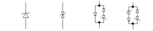
1, gas discharge tube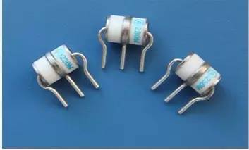
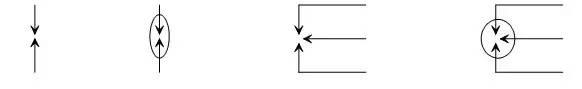
Figure 1 Schematic symbol of gas discharge tube
The gas discharge tube is a switching type protection device that works by gas discharge. When the voltage between the two poles is sufficiently large, the interelectrode gap will discharge and break down from the original insulation state to the conductive state, similar to a short circuit. The voltage maintained between the two poles in the conductive state is very low, generally 20 to 50V, so it can protect the circuit of the latter stage. The main indicators of the gas discharge tube are: response time, DC breakdown voltage, impact breakdown voltage, flow capacity, insulation resistance, interelectrode capacitance, and freewheeling interruption time.
Gas discharge tubes can have response times of hundreds of ns to several ms, the slowest in protective devices. When the lightning strike voltage on the cable causes the gas discharge tube in the lightning arrester to break through the short circuit, the initial breakdown voltage is basically the impact breakdown voltage of the gas discharge tube, and the sustain voltage drops between the two poles after the discharge tube is turned on and turned on. On the other hand, the flow rate of the gas discharge tube is larger than that of the varistor and the TVS tube. When the gas discharge tube is combined with the protection device such as TVS, most of the overcurrent should be discharged through the gas discharge tube. The gas discharge tube is generally used for the foremost stage of the protection circuit, and the protection circuit of the latter stage is composed of a varistor or a TVS tube. The response time of the two devices is fast, and the protection effect of the latter circuit is better. The insulation resistance of gas discharge tubes is very high and can reach the order of gigaohms. The value of the interelectrode capacitance is very small, generally below 5pF, and the leakage current between the poles is very small, which is nA level. Therefore, the gas discharge tube is connected to the line and does not have any influence on the line.
The freewheeling interruption of the gas discharge tube is an important consideration for the design circuit. As mentioned above, the gas discharge tube is continuously maintained at a voltage of 20 to 50 V in a conductive state. When applied in a DC power supply circuit, if the voltage between the two lines exceeds 15 V, the discharge tube cannot be directly applied between the two lines. When used in a 50 Hz AC power supply circuit, although the AC voltage has a zero crossing point, the freewheeling interruption of the gas discharge tube can be achieved, but the gas discharge tube type device will greatly reduce the freewheeling interruption capability after multiple conductive breakdowns. After long-term use, the free-wheeling interruption can not be realized at the zero-crossing point of the AC circuit; there is also a case that if the current and voltage phases are inconsistent, the freewheeling may not be interrupted. Therefore, it is not suitable to use the gas discharge tube separately between the phase line of the AC power supply circuit, the phase line to the neutral line, and the phase line. When the power equipment uses single-phase power supply, the phase line and the neutral line in the actual application cannot be guaranteed. When there is no possibility of reversal, it is not appropriate for the neutral line to use the gas discharge tube separately for the protective ground. In this case, the gas discharge tube needs to be connected in series with the varistor. The gas discharge tube is not substantially used in the protection of the phase line to the neutral line of the AC power supply circuit.
In the design of lightning protection circuit, attention should be paid to the selection of parameter values ​​such as DC breakdown voltage, impact breakdown voltage and flow capacity of the gas discharge tube. The discharge tube set on the ordinary AC line is required to be inoperable within the normal operating voltage of the line and its allowable fluctuation range, and its DC discharge voltage should satisfy: min(ufdc)≥1.8UP. Where ufdc DC breakdown voltage, min (ufdc) represents the minimum value of DC breakdown voltage. UP is the peak value of the normal operating voltage of the line.
The gas discharge tube can be mainly applied to the protection of the phase line and the neutral line of the AC power supply port; the protection between the DC RTN and the protection ground; the protection of the signal line line to the ground; and the protection of the shield layer by the antenna core of the antenna feed port.
The failure mode of the gas discharge tube is an open circuit in most cases, and the failure mode of the short circuit may also be caused when the discharge tube is short-circuited for a long time due to circuit design reasons or other factors. The life of the gas discharge tube is relatively short, and the performance will decrease after multiple impacts. At the same time, other discharge tubes may have a natural failure when the gas is used for a long time. Therefore, the lightning arrester composed of the gas discharge tube is used for a long time. There are problems with maintenance and replacement.
2, varistor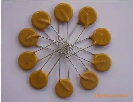

Figure 2 Schematic symbol of varistor
The varistor is a voltage limiting type protection device. Using the non-linear characteristics of the varistor, when an overvoltage occurs between the two poles of the varistor, the varistor can clamp the voltage to a relatively fixed voltage value, thereby protecting the latter circuit. The main parameters of the varistor are: varistor voltage, current capacity, junction capacitance, response time and so on.
The response time of the varistor is ns, which is faster than the air discharge tube and slightly slower than the TVS tube. Under normal circumstances, the response speed of the overvoltage protection for the electronic circuit can meet the requirements. The junction capacitance of a varistor is generally in the order of several hundred to several thousand pF. In many cases, it should not be directly applied to the protection of high-frequency signal lines. When it is used in the protection of an AC circuit, it will increase leakage due to its large junction capacitance. The current needs to be fully considered when designing the protection circuit. The varistor has a large flow capacity but is smaller than a gas discharge tube.
The varistor voltage (min (U1mA)) and the through-current capacity of the varistor should be considered in the circuit design. In the DC loop, there should be: min (U1mA) ≥ (1.8 ~ 2) Udc, where Udc is the DC rated operating voltage in the loop. In the AC loop, there should be: min (U1mA) ≥ (2.2 ~ 2.5) Uac, where Uac is the effective value of the AC operating voltage in the loop. The above value principle is mainly to ensure that the varistor has an appropriate safety margin when it is applied in the power supply circuit. In the signal loop, there should be: min (U1mA) ≥ (1.2 ~ 1.5) Umax, where Umax is the peak voltage of the signal loop. The flow capacity of the varistor should be determined according to the design specifications of the lightning protection circuit. In general, the varistor has a flow capacity greater than or equal to the flow capacity of the lightning protection circuit design.
The varistor can be mainly used for DC power supply, AC power supply, low frequency signal line, and antenna feeder with feed.
The failure mode of the varistor is mainly a short circuit. When the overcurrent passing through is too large, the valve piece may be broken and opened. The varistor has a short service life and will degrade after multiple impacts. Therefore, the lightning arrester composed of the varistor has problems of maintenance and replacement after being used for a long time.
3 Voltage Clamped Transient Suppression Diode (TVS)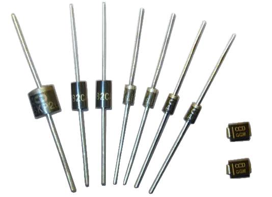
TVS (Transient Voltage Suppression) is a voltage-limiting protection device that functions like a varistor. It also protects the latter stage by clamping the overvoltage to a lower voltage value using the nonlinear characteristics of the device. The main parameters of the TVS tube are: reverse breakdown voltage, maximum clamping voltage, instantaneous power, junction capacitance, response time, and so on.
TVS' response time can reach ps level, which is the fastest of the limited voltage surge protection devices. When used for overvoltage protection of electronic circuits, the response speed can meet the requirements. The junction capacitance of the TVS tube can be roughly divided into two types according to the manufacturing process. The high junction capacitance type TVS is generally on the order of several hundred to several thousand pF, and the junction capacitance of the low junction capacitance type TVS is generally in the range of several pF to tens The order of magnitude of pF. Generally, the junction capacitance of the discrete TVS is high, and both types of surface-mounted TVS tubes are available. In the protection of high-frequency signal lines, TVS tubes with low junction capacitance should be mainly used.
The nonlinear characteristics of the TVS tube are better than those of the varistor. When the overcurrent through the TVS tube increases, the clamping voltage of the TVS tube rises faster than the varistor, so that a more reliable residual voltage output than the varistor can be obtained. . In many electronic circuits that require fine protection, the application of TVS tubes is a good choice. The flow capacity of the TVS tube is the smallest among the voltage limiting surge protectors. It is generally used for the fine protection of the last stage. Because of its small flow rate, it is generally not used for the protection of the AC power line, and the lightning protection circuit of the DC power supply. When using a TVS tube, it is generally required to use a device having a large current capacity such as a varistor. The TVS tube is easy to integrate and is ideal for use on a single board.
Another advantage of TVS is that it can flexibly use one-way or two-way protection devices. In the unipolar signal circuit and DC power supply circuit, the unidirectional TVS tube can be used to obtain a relatively low residual voltage.
The reverse breakdown voltage and current capacity of TVS should be considered in circuit design. In the DC loop, there should be: min(UBR)≥(1.3~1.6)Umax, where UBR is the reverse breakdown voltage of DC TVS, and Umax is the voltage peak in the DC loop.
TVS tube can be mainly used for lightning protection of DC power supply, signal line and antenna feeder line.
The failure mode of the TVS tube is mainly a short circuit. However, when the passing current is too large, the TVS tube may be broken and opened. TVS tubes have a relatively long service life.
4 voltage switching type transient suppression diode (TSS) Figure 4 Schematic symbol of the TSS tube
The voltage switching type transient suppression diode (TSS, Thyristor SurgeSuppressor) is the same as the TVS tube. It is also a voltage limiting protection device made by a semiconductor process, but its working principle is similar to that of a gas discharge tube, and is different from a varistor and a TVS tube. When the overvoltage across the TSS tube exceeds the breakdown voltage of the TSS tube, the TSS tube clamps the overvoltage to a level closer to 0V than the breakdown voltage, after which the TSS tube continues this short circuit until it flows through After the overcurrent of the TSS tube drops below the critical value, the TSS returns to the open state.
TSS is a voltage switching type transient suppression diode, which is a surge suppression transistor, or a conductor discharge tube, a solid discharge tube, and the like. LangTuo and other brands. The TSS tube is a protection device made by a semiconductor process and is mainly used for lightning protection of signal circuits. Cannot be used on the power port. TSS devices typically have a flow capacity of up to 150A (8/20uS).
Both the TSS tube and the TVS tube are voltage limiting protection devices made by a semiconductor process, and the TSS tube is a voltage switching type. TVS is a voltage clamp type. The TSS tube has the same characteristics as the TVS tube in response time and junction capacitance, and is easy to be fabricated into a surface mount device, which is suitable for use on a single board. The TSS tube is suitable for signal circuit protection with high signal levels.
The TSS tube has the same characteristics as the TVS tube in terms of response time and junction capacitance. It is easy to be used as a surface mount device. It is very suitable for use on a single board. After the TSS tube is activated, the overvoltage is pulled from the vicinity of the breakdown voltage to a level close to 0V. At this time, the junction voltage drop of the diode is small, so it is used for signal power. The higher the line (for example: analog subscriber line, ADSL, etc.), the protection flow rate is larger than the TVS tube, and the protection effect is better than the TVS tube. TSS is suitable for the protection of signal lines with high signal levels.
One problem to be aware of when using TSS tubes is that after the TSS tube breaks down under the action of overvoltage, the TSS tube returns to the open state after the current value flowing through the TSS tube drops below the critical value, so the TSS tube is in the signal. When used in a line, the normal current of the signal line should be less than the critical recovery current of the TSS tube. The critical recovery current value varies with the type and design of the TSS tube. When using it, please pay attention to the exact value of the specific model used in the device manual.
The breakdown voltage (min(UBR)) and current capacity of the TSS tube should be considered in the circuit design. In the signal loop, there should be: min (UBR) ≥ (1.2 ~ 1.5) Umax, where Umax is the peak voltage of the signal loop.
TSS tubes are mostly used for lightning protection of signal lines.
The failure mode of the TSS tube is mainly a short circuit. However, when the passing current is too large, the TSS tube may be broken and open. The service life of the TSS tube is relatively long.
5 positive temperature coefficient thermistor (PTC) The PTC is a current limiting protection device that has an operating temperature value TS. When the temperature in the body is lower than TS, the resistance remains substantially constant. The resistance at this time is called cold resistance. When the temperature of the positive temperature coefficient resistor body is higher than TS, the resistance value increases rapidly, and the maximum resistance value that can be achieved can be about 104 times higher than the cold resistance value. Since its resistance can increase rapidly with increasing temperature, it is generally used in series as an overcurrent protection for transient large currents. PTC has applications on both signal and power lines.
The PTC reaction speed is slow, generally above the millisecond level, so its nonlinear resistance characteristics can not play a role in the lightning overcurrent, and its current limit can only be estimated according to its normal resistance (cold resistance). The role of the thermistor is more often reflected in the occasion of long-term overcurrent protection such as power line contact, which is often used in the protection of subscriber lines.
At present, PTC mainly has two kinds of polymer materials: PTC and ceramic PTC. Among them, the overvoltage withstand capability of ceramic PTC is better than that of polymer material, but the PTC response speed of polymer material is faster than that of ceramic PTC. Generally, ceramic PTC cannot achieve low resistance, and low resistance PTC uses polymer materials.
6 fuses, fuses, air switchesThe fuses, fuses, and air switches are all protection devices. They can be used to disconnect short-circuit loads or over-current loads on the line in case of short-circuit or over-current faults inside the equipment, to prevent electrical fires and to ensure the safety characteristics of the equipment.
The fuse is generally used for protection on the board, and the fuse and air switch can generally be used for the protection of the whole machine. The following is a brief introduction to the use of fuses.
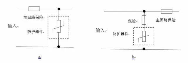
For the protection circuit composed of air discharge tube, varistor and TVS tube on the power supply circuit, it must be equipped with a fuse to protect the equipment from safety problems after the protection circuit inside the equipment is damaged. Figure 4-5 shows two examples of insurance applications. The protection circuit in the a circuit shares a fuse with the main circuit. When the protection circuit is short-circuited, the main circuit power supply will be disconnected at the same time. The main circuit and the protection circuit in the b circuit have The respective insurance, when the protection circuit fails, the protection circuit is disconnected, the main circuit can still work normally, but when the port is overvoltage again, the port may be damaged due to the loss of protection. Both circuits have their own advantages and disadvantages and can be selected as needed during the design process. It is not necessary to use a fuse for the protection of the feeder-free signal line and the antenna feeder line.
The characteristics of the fuse are mainly: rated current, rated voltage and so on. The rated voltage is divided into DC and AC.
The voltage rating marked on the fuse means that the fuse can safely and reliably interrupt its rated short-circuit current in a circuit with a voltage equal to or less than its rated voltage. The voltage rating series is included in N. E. C regulations, but also a requirement of the Underwriters Laboratories, as a protection against fire hazards. For most small-size fuses and micro fuses, fuse manufacturers use standard voltage ratings of 32, 63, 125, 250, and 600V.
In summary, a fuse can be used at any voltage less than its rated voltage without compromising its fusing characteristics. For the fuse in the protection circuit, an explosion-proof type slow-fuse fuse should be used.
7 inductance, resistance, wireThe inductor, the resistor, and the wire itself are not protection devices, but they can play a role in the protection circuit composed of a plurality of different protection device combinations.
Among the protective devices, the gas discharge tube is characterized by large flow rate, but slow response time and high impact breakdown voltage; the TVS tube has a small flow rate, the fastest response time, and the best voltage clamping characteristics; the characteristics of the varistor Between the two, when a protection circuit requires a large overall flow rate and can achieve fine protection, the protection circuit often needs these kinds of protection devices to achieve ideal protection characteristics. However, these protective devices cannot be simply used in parallel. For example, a varistor with a large flow rate and a TVS tube with a small flow rate are directly connected in parallel. Under the action of an overcurrent, the TVS tube will be damaged first, and the varistor cannot be utilized. The advantage of large flow. Therefore, in the case of using several protective devices, it is often necessary to cooperate between different protective components such as inductors, resistors, wires, and the like. The following describes each of these components:
Inductance: In the series DC power supply protection circuit, there should be no large voltage drop on the feeder. Therefore, the inter-pole circuit can be equipped with a hollow inductor, as shown below:
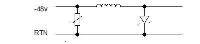
Figure 6 Using an inductor to achieve the coordination of two levels of protection devices
The role of electrical induction: When the protection circuit reaches the design flow rate, the overcurrent on the TVS should not reach the maximum flow rate of the TVS tube, so the inductor needs to provide sufficient current limiting capability for lightning overcurrent.
In the power circuit, the design of the inductor should pay attention to several problems:
1. The inductor coil should work normally without overheating when flowing through the fully equipped operating current of the device;
2. Try to use the hollow inductor. The inductor with the magnetic core will be magnetically saturated under the action of overcurrent. The inductance in the circuit can only be calculated by the inductance without the core.
3, the coil should be wound as much as possible, which can reduce the parasitic capacitance of the coil, and at the same time enhance the resistance of the coil to transient over-voltage;
4. The insulating layer on the wire of the wound inductor coil should have sufficient thickness to ensure that the breakdown of the coil does not occur under the action of transient over-voltage.
In the protection circuit design of the power port, the inductance is usually 7~15uH.
Resistance: In the signal line, the components connected in series on the line should have as little suppression as possible on the high-frequency signal. Therefore, the resistor can be used for the inter-pole coordination, as shown in the following figure:
 Figure 7 Using a resistor to achieve the coordination of two levels of protection devices
The function of the resistor should be substantially the same as that of the aforementioned inductor. The above figure is an example. The calculation method of the resistance is: measuring the impact breakdown voltage value U1 of the air discharge tube, checking the TVS device manual to obtain the maximum through flow I1 of the TVS tube 8/20us inrush current and the highest clamp of the TVS tube. For the bit voltage U2, the minimum value of the resistor is: R≥(U1-U2)/I1.
In signal lines, there are several issues to be aware of when using resistors:
1. The power of the resistor should be large enough to avoid damage to the resistor under overcurrent;
2. Try to use a linear resistor as much as possible to minimize the effect of the resistor on normal signal transmission.
Wire: The full-scale working current of some AC/DC equipment is very large, exceeding 30A. In this case, the interference between the poles of the protection circuit and the inductor will be too large. To solve this problem, the protection circuit can be divided into two parts. In the two parts, the front-level protection and the rear-level protection are not designed on the same circuit board, and the feeders of the specified length can be used for cooperation between the two-stage circuits.
 Figure 8 uses wire to achieve the coordination of two levels of anti-devices
In the protection circuit formed by the combination, the function of the specified length of the feeder is the same as that of the inductor, because the inductance of the 1 meter long wire is between 1 and 1.6 uH, and the feeder reaches a certain length, It plays a good role in cooperation. The wire diameter of the feeder can be flexibly selected according to the size of the full working current, which overcomes the shortcoming that the inductor can not flow a large working current when the pole is matched.
8 transformers, optocouplers, relaysTransformers, optocouplers, and relays are not themselves protective devices, but the design of port circuits can take advantage of the isolation characteristics of these devices to improve the port circuit's ability to withstand overvoltage.
There are two ways to design a port lightning protection common mode protection:
1. Install a voltage limiting protector on the line to the ground. When the line introduces a lightning overvoltage, the voltage limiting protector becomes a short circuit state and discharges the overcurrent to the earth;
2. The isolation component is designed on the line, and the circuits on both sides of the isolation component are not common. When the circuit introduces a lightning overvoltage, the transient overvoltage is applied to both sides of the isolation component. As long as the overvoltage acts on the isolation element, the isolation element itself is not broken down by insulation, and the high voltage signal line of the isolation element does not break down to other low voltage parts, the lightning overvoltage on the line cannot be converted into overcurrent into the device. The internal circuitry of the device is also protected. At this time, only differential mode protection needs to be designed on the line, and the protection circuit can be greatly simplified. For example, the protection of the Ethernet port can adopt this idea. The components that can achieve this isolation are: transformers, optocouplers, and relays.
The transformer here mainly refers to various signal transmission transformers for signal ports. The transformer generally has an initial/secondary insulation withstand voltage. The impulse withstand voltage of the transformer (for lightning strikes) can be converted according to the DC withstand voltage value or the AC withstand voltage value. The approximate estimation formula is: impact withstand voltage = 2 × DC withstand voltage = 3 × AC withstand voltage value.
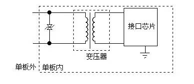 Figure 9 is isolated with a transformer
The figure above shows a signal port protection circuit design that incorporates a transformer. When lightning strikes, the common-mode over-voltage induced on the cable outside the device acts between the primary and secondary of the transformer, as shown in Figure 9. As long as the primary/secondary insulation breakdown does not occur, the overvoltage on the cable outside the device will not be converted into an overcurrent into the device. At this time, the port only needs to be differential mode protection, and the isolation characteristics of the device such as a transformer are used to simplify the lightning protection circuit of the port.
The design of this method should be noted that the insulation withstand voltage of components such as transformers, optocouplers and relays should be very high (for example, the withstand voltage is greater than 4kV), otherwise insulation breakdown will easily occur under the action of overvoltage. Can not play the role of improving the port withstand voltage. In addition, when using the isolation characteristics of the transformer, it is necessary to pay attention to the distributed capacitance between the primary/secondary of the transformer. In some cases, the common mode overvoltage on the external cable can be coupled from the primary to the secondary through the distributed capacitance, thereby entering the internal In the circuit, this destroys the isolation effect of the transformer. Therefore, the transformer with the primary interpole shield should be used as much as possible, and the outer lead of the transformer shield is grounded in the board, as shown in Figure 9. At this time, the effective insulation withstand voltage of the transformer becomes the insulation withstand voltage between the primary and the shield ground. Another problem to be aware of when using a common mode isolation design is that the primary circuit should be separated from the other circuits on the board and the ground traces on the board and have sufficient insulation distance. Generally, two printed traces with a 1 mm edge on the printed board can withstand a shock voltage of about 4 kV of 1.2/50us.
Socket Connector,Board-To-Board Socket Connectors,Horizontal Socket Connector,Screw Male Socket Connector
Shenzhen Jinyicheng Electronci Technology Co.,Ltd. , https://www.jycconnector.com