Currently, there are three main ways to generate SPWM signals:
1) Using analog circuits such as comparators and oscillators to generate triangular waves and square waves for comparison, and generating SPWM waves, but this method is complicated in circuit, greatly affected by component accuracy, and difficult to control;
2) Using the dedicated SPWM integrated chip, the advantage is that the circuit is simple and the integration is high. The disadvantage is that the feedback control, monitoring management and protection work of the system cannot be fully realized, so it is generally required to cooperate with the single chip microcomputer;
3) Using a microprocessor such as a single chip to generate SPWM waves, the control circuit is simple, flexible, and low in hardware cost. This paper introduces a method to realize SPWM waveform by using PIC16F877A single-chip microcomputer, and applies it to the full-bridge inverter circuit to verify the feasibility of modulating SPWM wave with PIC microcontroller.
1, the overall design of the systemThe system is mainly composed of a single-chip control circuit, a drive and an inverter main circuit.
1.1, single chip control circuit1.1.1, PIC16F877A MCU main function introduction
The main resources and functions of this series of microcontrollers are:
1) 3 timers, 2 8 bits, 1 16 bits;
2) 8-channel 10-bit A/D converter, 1 reference voltage generator, 2 analog voltage generators;
3) 368 bytes (368 & TImes; 8 bits) of data memory;
4) Power-on reset (POR), brown-out reset (BOR);
5) 2 CCP modules with capture, comparison and pulse width modulation functions;
6) There are two 8-bit Timer/Event Counters TMR0, TMR2 and a 16-bit Timer/Event Counter TMR1, where TMR2 has a divider, a postscaler and a period register. TMR2 is also the time base in the PWM mode of operation in the CCP module.
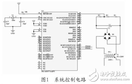
1.1.2, system control circuitThe system uses the CCP modules CCP1 and CCP2 of the series to output two complementary SPWM waves, and then generates four signals through the inverter to the driving circuit. The inverter output voltage has a voltage stabilization feedback function, which is realized by connecting the single chip microcomputer RA0/AN0. The system control circuit is shown in Figure 1.
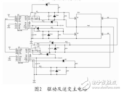
The system adopts full-bridge inverter form, and the main circuit of drive and inverter is shown in Figure 2. When Q1 and Q4 are turned on, Q2 and Q3 are turned off; when Q2 and Q3 are turned on, Q1 and Q4 are turned off. The driver chip adopts IR2110. This chip has the advantages of optocoupler isolation and electromagnetic isolation. The floating power supply adopts bootstrap circuit, independent power ground and logic ground, which makes the chip structure more reliable.
Shenzhen Kaixuanye Technology Co., Ltd. , https://www.iconline-kxy.com