Design and Implementation of ZigBee Technology Voice and Image Wireless Monitoring System
When the environment is harsh, and factors such as temperature, pressure, humidity, vibration, noise, and electromagnetics may change at any time, the use of general network technology to build a monitoring system may result in insufficient real-time performance, low sensitivity, and delay Large, short distance, low reliability, obvious environmental restrictions and other defects, can not fully and effectively realize safety monitoring in real time. With the rapid development of microelectronics technology, digital technology, network and communication technology, wireless sensor network has gradually become a monitoring system due to its advantages of low cost, flexible networking, less geographical restrictions, strong concealment, and unattended operation. Preferred.
In wireless sensor networks, the low-rate and short-distance ZigBee technology is one of the preferred technologies for wireless communication. This design uses Zigbee technology as the starting point to ensure safe real-time monitoring and wireless transmission of voice and images based on wireless sensor network nodes.
The composition of ZigBee technology voice and image wireless monitoring system
The system consists of two parts: two-way wireless transmission of voice and wireless transmission of images, so that the staff can easily monitor some harsh environments in the monitoring center, timely handle various operational accidents, and ensure operational safety.
1 ZigBee technology realizes wireless transmission of voice
â‘ Overall structure of voice wireless transmission system The wireless transmission of voice is based on an embedded microprocessor and a radio frequency transceiver module, supplemented by external amplifiers, filter circuits, and audio codecs. The overall structure is shown in Figure 1.

Figure 1 Overall block diagram of voice wireless transmission
The operational amplifier is responsible for amplifying and eliminating some interference of the voice signal received by the microphone; the audio codec completes the A / D and D / A conversion of the voice signal and the encoding and decoding of the audio signal; the embedded microprocessor is responsible for storage and processing The data collected by itself and the data sent by other nodes coordinate the communication with other nodes; the RF transceiver module is responsible for wireless communication with other nodes, exchange control information, and complete the reception and transmission of data; the power amplifier decodes and D / The analog voice signal after A conversion is amplified and restored to the original data signal and output by the speaker.
â‘¡ Selection of voice wireless transmission system components
The embedded microprocessor selects TI's low-power fixed-point high-performance TMS320VC5416. The DSP uses dual power supplies, which are the core power supply 1.6V and the I / O power supply 3.3V. The main features are: speed up to 160MIPS; 3 16bit data memory buses and 1 program memory bus; 1 40bit barrel shifter and 2 40bit accumulators; 1 17 × 17 multiplier and 1 40bit dedicated addition Device; maximum 8M × 16bit extended addressing space, built-in 128K × 16bit RAM and 16K × 16bit ROM; 3 multi-channel buffered serial ports (McBSP); equipped with PCM 3002 low power monolithic stereo audio codec, Can carry on A / D and D / A conversion to the pronunciation.
The RF transceiver module selects IP-Link 1221-2264 that conforms to the IEEE802.15.4 standard. The module works in the 2.4GHz band and the communication rate can reach 250kb / s. It can provide high-efficiency and long-distance online capability, high output power and low signal sensitivity. Suitable for wireless communication solutions in long distances and harsh environments. The module includes general-purpose I / O port, asynchronous serial interface, JTAG port, USB port, external power supply interface, etc. Among them, the USB port is responsible for communicating with the PC and supplying power to the node. The external power supply interface supports 2.7 to 3.6V DC power supply, and there are also two A / D and two D / A converters.
The audio codec uses TLV320AIC23 produced by TI. The core digital power supply voltage 1.42 ~ 3.6V, analog power supply voltage 2.7 ~ 3.6V, are compatible with TMS320VC5416, so that TLV320AIC23 and TMS320VC5416 can be directly connected without the need for other level conversion chips; built-in headphone amplifier, supports stereo lines There are two ways of input and microphone input, and programmable gain adjustment for input and output; the A / D conversion and D / A conversion components of TLV320AIC23 are integrated in the chip, using advanced sigma-delta oversampling technology, which can be 16bit, 20bit, 24bit and 32bit sampling are provided in the range of 96kHz, and the output signal-to-noise ratio of the ADC and DAC can reach 90dB and 100dB, respectively.
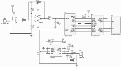
Figure 2 System hardware circuit
The operational amplifier consists of two parts: an amplifier circuit and a filter circuit. The amplifying circuit uses low-power, low-cost LMV324 amplifier, plus low-pass filter circuit composed of R and C.
The power amplifier uses LM386. It is a kind of audio set that has the advantages of low power consumption, adjustable voltage gain, large power supply voltage range, few external components and low total harmonic distortion. It adds an external resistor and capacitor between pins 1 and 8. , You can adjust the voltage gain to any value between 20 and 200.
â‘¢Hardware circuit implementation of voice wireless transmission system
The voice signal obtained by the microphone is amplified and sent to the microphone input terminal (MICIN) of TLV320AIC23. After A / D conversion and audio coding, two multi-channel buffered serial ports McBSP0 and McBSP1 complete control and communication. The McBSP2 of TMS320VC5416 is expanded to an asynchronous serial interface, and then sends the signal to the asynchronous serial interface of the RF transceiver module, which is modulated by the carrier signal and sent out by the transmitting antenna. The receiving process is the reverse of the above process. The specific hardware circuit is shown in Figure 2.
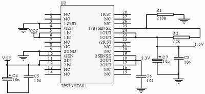
Figure 3 power circuit
In the hardware circuit, the use of 1.6V and 3.3V two sets of power supply, here choose the dual output LD0 regulator TPS73HD301 (see Figure 3). TPS73HD301 is a two-output power chip provided by TI. The output voltage is 3.3V all the way, and the adjustable output is 1.2 ~ 9.75V all the way.
2 ZigBee technology realizes wireless image transmission
The wireless transmission of images takes the radio frequency transceiver module as the core, supplemented by external cameras and level conversion chips. The overall hardware structure is shown in Figure 4.
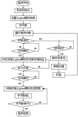
Figure 5 Flow chart of data sending and receiving
The image data output from the camera has been well compressed with a rate of tens of kb / s, so this system uses the RS-232 serial port for communication. Because the level of the RS-232 serial port is higher, it must be sent to the asynchronous serial port of the radio frequency transceiver module after MAX3232 level conversion, and sent out by modulation. The radio frequency transceiver module of the receiving end is directly inserted into the host computer through the USB port to realize communication with the host computer and supply power to the node.
Because the power supply voltage of the camera is 12V, and the power supply voltage of the RF transceiver module is 2.7 ~ 3.6V, this system uses 12V and 3.3V power supply.
System software design
In the design of the system software, the node adopts the serial communication mode, and uses the interrupt method to complete the data reception and transmission. The data transmission adopts the master-slave node mode, and the USB interface is used to communicate with the PC. The data to be sent is packed according to the maximum frame length specified by the Zigbee protocol, plus the frame headers of the network layer, media access control layer and physical layer, and the data is sent to the RF transceiver module of the receiving end according to user requirements through the SPI bus. When the slave node sends an interrupt request to the master node, it automatically transfers to the interrupt service subroutine to realize the reception of information packets and data processing. The data sending and receiving process of this system is shown in Figure 5.

Figure 6 Simulation results of image wireless transmission
Simulation results and application in industrial control
The monitoring management software written in Java is used on the monitoring end, and the serial port, baud rate, delay time, infrared light, picture size, image transmission time and other aspects are adjusted to send monitoring commands to the wireless sensor network and receive sensor data information to achieve The processing, reception, storage and display of image data present a large amount of sensory data from the wireless sensor network to the staff in an intuitive way. The simulation results are shown in Figure 6.
With the progress and development of society, safety issues are the primary emphasis in the industrial production process. In those dangerous industrial environments such as mines, nuclear power plants, and steel processing plants, the system can be used for process monitoring and safety inspections. In the industrial automation production line, the use of this system can greatly improve the operating conditions of the factory and greatly reduce the cost of inspection equipment. At the same time, because problems can be discovered in advance, it can reduce the losses caused by production accidents, promote the smooth progress of production, shorten equipment downtime, improve efficiency, and extend equipment use time.
Conclusion
The simulation results show that the system can achieve real-time wireless transmission of voice and images in tunnels, coal mines and other harsh environments. It has reliable work, complete performance, high overall cost performance, and has wide application prospects. It can also be applied to factories, banks, supermarkets, prisons, hotels, shopping malls and other fields, and has certain promotion value.
Electric Hydrofoil Propulsion System is a powerful Underwater Jet System, Application to hydrofoil , surfboard,small fishing boats ,Even you can use it for diving booster. Our Electric hyrdofoil propulsion system is a Tunnel Jet type propulsion system. With the protective shield on both side, these type design can keep the propeller safe ,avoid Accidental inhalation of the grass, fishes. High efficiency brushless motor with the propeller get the lower working current and long continuouse working time. This is quite different of our proulsion system to compare with other oridinary tunnel jet systems. We use the boat ESC as the controller ,and it is only 150A , we controled our tunnel jet engin working with lowercurrent .reduce the cost and improve the system life. economy for maintenance and repair.The system shell made by Aluminium Alloy 6061,light weight, small size but powerfull thrust.

Electric Hydrofoil Propulsion System
Underwater Jet System,Electric Tunnel Thruster,Electric Underwater Boat Propulsion System
shenzhen GC Electronics Co.,Ltd. , https://www.jmrdrone.com