1 Introduction
The starting of the automobile engine is achieved by the starter driving the engine flywheel to rotate. The drive gear of the starter driven by the battery produces mechanical motion; the transmission mechanism meshes the drive gear into the flywheel ring gear and can be automatically disengaged after the engine is started; the starter DC motor is controlled by an electromagnetic switch. The car starter is a valuable part in the car and will not be easily damaged. However, in order to extend the life of the starter, there must be an appropriate method of use. Due to misoperation, etc., when the automobile engine is started, if the starter cannot be powered off in time after the engine is started. It will burn the starter or damage the flywheel ring; if the transmission is not in neutral when starting, it will cause traffic accidents and personal safety. In the process of starting the engine, the starter should draw 300-400 Ah of electricity from the battery. In order to prevent the battery from overcurrent or damage, the starting time should generally not exceed 5 s; in winter, it is prone to start difficult, many times Each starting time should not be too long when starting, and appropriate intervals should be left for each starting.
In order to achieve the normal start and safety protection of the engine, it needs to be considered from the automobile electrical control system. In the starting circuit system of a car engine, the power supply of the car starter comes from the battery. When the engine starts, the current of the starter coil is very large, reaching hundreds of amperes. In order to ensure that the car engine can start normally, usually when the engine is started, it is required to cut off the power supply of body electrical appliances such as car lights, and only to provide power for the car starter. In order to prevent a safety accident when the car starts, the car engine can only be ignited and started when the gearbox of the car is in the neutral state, otherwise the car will be displaced due to the instantaneous strong rotation of the starter, and there will be damage once there is an obstacle Cars may endanger personal safety. In order to protect the starter, each start must not exceed a certain time. If the continuous running time of the car starter with load exceeds 5 to 8 s, the start switch does not turn off after the engine starts, and the starter continues to work, the flywheel gear will drive the starter drive The gear rotates at high speed, which accelerates and damages the one-way clutch of the starter. If the start switch is turned on by mistake after the engine is started, the starter drive gear will collide with the high-speed rotating flywheel and damage the starter. Therefore, it cannot be restarted under the condition of engine start. Here, a car starting protection controller based on NXP P89LPC901 single-chip is introduced. The controller detects and controls the starting process of the automobile engine. By using the power supply system to turn off or turn on the load one by one, it solves the impact of the starting current on the automobile power supply. , To protect the car starter.
2 Working process and functions of the start protector
2.1 Working process
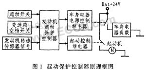
Figure 1 shows the functional block diagram of the automobile starter protector. The working process is: the start protection controller detects the start switch. When the start switch is turned on, if the gearbox position switch is in the neutral position, and the car engine is not in working state, turn on the body electrical power relay to cut off the body Electrical load power, after a delay of 0.5 s, the start control relay is turned on, and the starter is powered on to start. When the start switch is turned off or the engine speed reaches 300 r / min, the controller releases the start control relay, the starter is powered off and stops working, after a delay of 0.5 s. Release the power supply relay of the body electrical appliances, connect the load power of the body electrical appliances, and the start is completed.
2.2 Main functions
2.2.1 Normal start
When the key switch is turned from the ON position to the (start position) START position to start the engine, when the transmission gear is in the neutral position, the start protection controller first cuts off the power supply of the body electrical load, and the delay is 0.5 s. Turn on the start relay again, the starter starts, when the starter drives the engine to rotate, the engine speed is greater than 300 r / min, or when the key switch returns from the START position to the ON position, the controller controls the start relay to be disconnected, and the starter is powered off , Delay 0.5 s, then turn on the power supply of the body electrical load, and the starting process is completed.
2.2.2 Non-neutral start protection
The start protector requires that the gearbox can only start the engine when it is in the neutral position. However, if the neutral switch is damaged or the driver knows that the gearbox is not in the neutral position but must start the engine, the non-neutral position can be adopted to protect the start. The starting condition is that the key is required to go from the ON position to the START position, and in the START position Start after 3 s. The starting process is the same as normal starting.
2.2.3 Key switch can not return protection
During the start of the car, if the key switch is in the START position and the time is greater than 5 s, or due to the failure of the key switch, it is not possible to return from the START position to the ON position within 5 s. In order to protect the starter and the battery, the controller can be cut off Starter power supply, connect the power supply of the body electrical load.
2.2.4 Repeated start protection
If the engine is already in operation and the speed is greater than 300 r / min, when the key switch is turned from ON to START, the controller ensures that the starter will no longer start.
3 Main features of P89LPC901 microcontroller
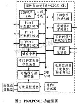
According to the working conditions and reliability requirements, after comparison, the single-chip packaged microcontroller produced by NXP Company, namely the NXP P89LPC901 single-chip microcomputer, is selected. The operating temperature range of the single chip microcomputer is -45 ~ 85 ℃, therefore, it can meet the application requirements of automotive starter protectors. The main performance of the single-chip microcomputer is: due to the use of high-performance processor structure and enhanced 8051 core. Its instruction execution speed is 6 times faster than standard 80C51 devices, therefore, it integrates many system-level functions. Figure 2 shows the structure and functional block diagram. The chip integrates 1 KBFlash program memory, 128 B data memory, two 16-bit timer / counter and PWM, 23-bit system timer, and enhanced UART, with high-precision internal RC oscillator and on-chip reset, 8 lead Foot SO-8 package, up to 6 programmable I / O ports, an internal programmable analog comparator, programmable Watchdog timer and power monitor, etc. This single-chip microcomputer has a high performance-price ratio and can meet The control function requirements of the car start protector.
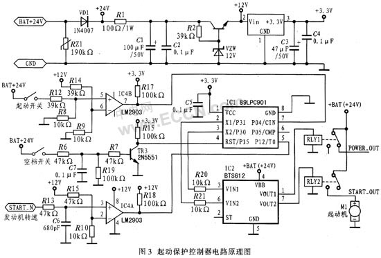
4 Starter protector circuit principle According to the functions and working process requirements of the car starter protector, the car starter protector circuit using the NXPP90LPC901 single-chip is controlled by the power supply circuit, single-chip circuit, switch signal input circuit, engine speed input circuit, power supply relay and starting relay The circuit and other components (see Figure 3). P89LPC901 adopts internal reset circuit and on-chip RC oscillator (7.373 MHz), can provide 6 programmable I / O interfaces, which are used for input detection and output control respectively.
4.1 Power circuit
Start protection controller for passenger cars. The power supply uses a +24 V car battery power supply. After a varistor and a protection diode VD1 that prevents the power supply polarity from being reversed, a +12 V voltage is obtained. This voltage is the power supply for the comparator LM2903, and the voltage is filtered to limit current After that, it is stabilized and filtered by the HA7355 regulator tube, and then a +3.3 V voltage is provided to the P89LPC901.
4.2 Switch input detection circuit
The input switches of the start protection controller are: start switch (START-SW), neutral switch (NULL-SW); 2 binary input signals, which are valid when connected to the positive power supply (+24 V).
The power supply for the starter comes from the car battery. When the starter starts, the current is very large, which can reach hundreds of amps, which may cause the battery to lose power and reduce the voltage. In order to ensure that when the start switch is turned on, the battery voltage is greater than 12 V, it can start normally, so that the START-SW signal is converted by the comparator LM2903 and connected to the P04 pin of the single-chip computer. When the START-SW signal voltage is greater than 12 V, the 7th pin of the LM2903 outputs +33 V; when the START-SW signal voltage is greater than +12 V, the 7-pin of the LM2903 outputs 0 V.
The NULL-SW signal of the neutral switch is converted into the level signal required by the single-chip microcomputer through the transistor conversion circuit, and then connected to the P15 pin of the single-chip microcomputer. When the neutral switch is turned on, the P15 pin of the single-chip microcomputer is high; when the neutral switch When disconnected, the P15 pin of the microcontroller is low.
4.3 Engine speed sensor input detection circuit The engine speed sensor outputs a sinusoidal signal with a voltage amplitude range of 3 to 6 V. The engine output signal is 173 pulses / rev. When the engine speed is greater than 300 r / min, the start is completed. The sine signal output by the engine speed sensor is converted into a square wave signal by the comparator LM2903 and connected to the P12 pin of the microcontroller, that is, the counter input pin of the P89LPC901. When the signal output by the engine speed sensor is greater than 2 V, it is high; Low level at 2 V.
4.4 Relay control circuit
In the control circuit, the power supply of the body electrical appliances is controlled by the relay RLY1, so that the load is connected to the normally closed contact; the starter start control is through the relay RLY2, and the load is connected to the normally open contact. The relay in the circuit is output by P30 and P31 of 89LPC901, and is amplified and driven by BTS612.
5 Starting protection controller control program
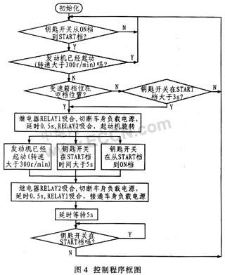
The starting protection controller control program is written in assembly language. Figure 4 shows a block diagram of a control program designed according to the engine's starting process and functional requirements.
6 conclusions The car starting protection controller circuit designed considers the environment and reliability of the car. It is controlled by NXP 89LPC901 single-chip microcomputer. It has the advantages of simple control circuit design, flexible control, high reliability and low cost. More than 50,000 vehicles have been installed on Yutong buses. It has been proved to be stable and reliable and runs well.
Electric Tea Kettle:
Quickly brew the perfect
cup of tea or make pour over coffee right at the table with the Electric Tea
Kettle. With 1500 watts, this Electric Kettle boils water faster than a
microwave, and is safer to use than a stovetop kettle because it automatically
turns off when the water reaches a boil. Serving at the table is no problem as
the kettle lifts off the base without the cord. Additional features include two
water level windows and a pull-lid to make filling and serving easy.
Features:
-
Thermostat Control – Having
a thermostat control allows the kettle to [know" when to shut off. This will
prevent damage to the heating element and is an important feature in all modern
styles.
-
Auto shut off/Boil Dry Protection/Fuse –
these are three features that are great for protecting the safety of users as
well as extending the life of the electric kettle. The fuse and boil dry
protection shut the kettle off if the water gets down below a certain level or
if it`s left on for an extended period of time, It doesn`t burn up the kettle.
-
Colors and Designs – Electric kettles
come in all shapes, sizes and colors. Finding one that will fit with the
kitchen design is actually pretty easy. Finding one that matches and that
has the features you`re looking for can be a bit harder, but with all the
choices available and the newer models on the market today, you will be able to
find the perfect electric kettle for your kitchen.
-
Savety
in Electric- the heating element is
typically fully enclosed, with a power rating of 2–3 kW at 220V. In
countries with 110V mains electricity, kettles may be less powerful (1–1.5 kW)
to avoid drawing too much current and requiring a very thick supply wire.
Application:
Heat
the tea thoroughly
Bottle
the water/beer
Boil
water
Electric Tea Kettle
Electric Tea Kettle,Stainless Steel Electric Tea Kettle,Cordless Electric Tea Kettle,Electric Cordless Glass Tea Kettle
Guangzhou Taipeng Electrical Appliances Technology CO., LTD. , https://www.kettles.pl