Overview The MAX6956 LED driver and I / O expander can provide and maintain the desired constant current for all 20 or 28 LED drive ports (depending on the package type) without external current limiting resistors. All ports can be set at the same time, with sixteen constant currents (from 1.5mA to 24mA); or each port can be set to a different constant current. The MAX6956 not only has LED brightness control, but also the port matching accuracy of the device ensures that the chromaticity will be more consistent. In addition to the constant current LED driver, each independent port of the MAX6956 can also be used as an input port with transient detection, or a push-pull output port with 10mA sink current and 4.5mA source current.
The MAX6957 is similar to the MAX6956, but uses SPI ™ instead of an I²C compatible interface. The MAX7300 is a general-purpose I / O (GPIO) port expander similar to the MAX6956, but the device does not have a constant-current LED drive function. The MAX7301 is a GPIO port expander similar to the MAX7300, but the device uses an SPI interface instead of an I²C compatible interface.
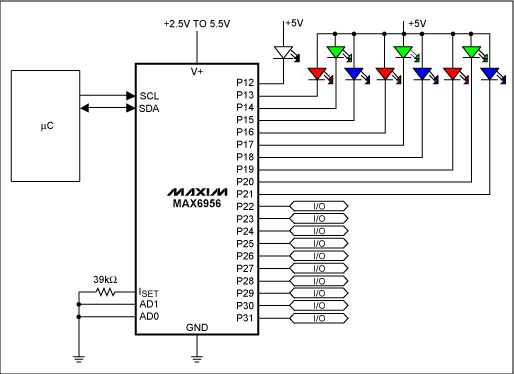
Figure 1 shows a simple application example of using MAX6956 to drive ten white and RGB LEDs without a current limiting resistor.

Figure 1. MAX6956 application circuit
The specific operation of MAX6956 configuration register MAX6956 is controlled by writing to 89 registers. In addition to the four registers described in the data sheet (global current, configuration, transient detection Mask, and display test), the MAX6956 has three other register sets: Port configuration (0x09 to 0x0F)
Each port in the port configuration register is divided into two bits. These two bits can define each port as LED driver, output port or input port with / without pull-up resistor. Corresponding to 28 ports, there are 7 port configuration registers. Independent current (0x12 to 0x1F)
Each port in the independent current register is divided into four bits. These four bits can define each independent port to the desired constant current. The minimum step size is 1/16 of the maximum current value set by the external resistor connected to the ISET pin. Port I / O value (0x20 to 0x5F)
The device has 29 port I / O value registers for each independent port (port 31 has two registers). There are 21 port I / O value registers that can be used to simultaneously define 8 different ports as a group of I / O values. Other port I / O value registers can be used to define 2, 3, 4, 5, 6 or 7 different ports as a group at the same time. MAX6956 I²C command The following gives the I²C command to set all ports to half the maximum constant current of 24mA (with 39kΩ external resistor) at power-up. When both AD0 and AD1 pins are connected to ground, the MAX6956 I²C device address is 0x80. The I2CWrite routine uses the register address auto-increment feature to write a specific byte to a MAX6956 register or a command to write multiple bytes to a series of consecutive registers.
I2CWrite (0x80, 0x02, 0x07); // Set a half global constant current I2CWrite (0x80, 0x09, 0x00, 0x00, 0x00, 0x00, 0x00, 0x00, 0x00); // Set all ports to LED drive mode I2CWrite (0x80 , 0x04, 0x01); // Set the shutdown / run bit of the configuraTIon register
As a reference checkpoint, the equivalent binary number for setting the shutdown / run bit write command is listed below. I2CWrite (0x80, 0x04, 0x01); 1 0 0 0 0 0 0 0 0 0 0 0 0 0 1 0 0 0 0 0 0 0 0 0 1
The following shows the I²C command to set a port (P4 in this example) to full-scale constant current at power-up. I2CWrite (0x80, 0x12, 0x07); // Set a half port P4 constant current I2CWrite (0x80, 0x09, 0xA8); // Set P4 to LED drive mode I2CWrite (0x80, 0x04, 0x01); // Set the shutdown / run bit of the configuraTIon register
At power-up, all ports are set to logic inputs without pull-up resistors. Only the following I²C commands are required to set the MAX6956 to work in all power-on default states. I2CWrite (0x80, 0x04, 0x01); // Set the shutdown / run bit of the configuraTIon register
MAX6957 SPI command Any register of the MAX6957 can send or read the 16-bit word containing the register address and the data byte immediately following the SPI interface. The first bit of the address byte determines whether it is a write (0) command or a read (1) command. All 16-bit words can be placed together with other words.
The data byte on the MAX6957 DIN input pin is given below to set all ports to half of the 24mA maximum constant current. These commands are similar to the MAX6956, except that the device address needs to be specified. For the SPI interface, a specific device can be selected by setting the active CS input pin low. The MAX6957 does not have an auto-increment function for register addresses. 0x02, 0x07; // Set a half global constant current 0x09, 0x00; // Set ports P4 through P7 to LED drive mode 0x0A, 0x00; // Set ports P8 through P11 to LED drive mode 0x0B, 0x00; // Set ports P12 through P15 to LED drive mode 0x0C, 0x00; // Set ports P16 through P19 to LED drive mode 0x0D, 0x00; // Set ports P20 through P23 to LED drive mode 0x0E, 0x00; // Set ports P24 through P27 to LED drive mode 0x0F, 0x00; // Set ports P28 through P31 to LED drive mode 0x04, 0x01; // Set the shutdown / run bit of the configuraTIon register
The MAX7300 / MAX7301 configuration registers MAX7300 and MAX7301 do not have constant current LED drive capability. Control the detailed working status of the device by writing 73 registers. In addition to the configuration and transient detection mask registers, there are two other sets of registers: Port configuration (0x09 to 0x0F) Port I / O value (0x20 to 0x5F) When the MAX7300 I²C command is powered on, all ports are set Logic input with pull-up resistor. The following shows the I²C command to set P14 to P23 to half the port full current when the output is logic high, and to put the chip from the initial shutdown to the working state. When the AD0 and AD1 pins are connected to ground, the MAX²300 ’s I²C device address is 0x80. I2CWrite (0x80, 0x0B, 0x5A, 0x55, 0x55); // Set P14 through P23 to output I2CWrite (0x80, 0x4E, 0xFF); // Set P14 through P21 to logic high I2CWrite (0x80, 0x56, 0x03); // Set P22 through P23 to logic high I2CWrite (0x80, 0x04, 0x01); // Set the shutdown / run bit
MAX7301 SPI command Any register of the MAX7301 can send or read a 16-bit word containing the register address and the next data byte through the SPI interface. The first bit of the address byte determines whether it is a write (0) command or a read (1) command. All 16-bit words can be placed together with other words.
The following shows the data byte on the MAX7301 DIN input pin. When the output is at a logic high, set P14 to P23 to half of the port current, and make the chip enter the working state from the initial shutdown. These commands are similar to the MAX7300, except that the device address needs to be specified. For the SPI interface, a specific device can be selected by setting the active CS input pin low. The MAX7300 does not have automatic register address increment function. 0x0B, 0x5A; // Set P14 and P15 to output 0x0C, 0x55; // Set P16 through P19 to output 0x0D, 0x55; // Set P20 through P23 to output 0x4E, 0xFF; // Set P14 through P21 to logic high 0x56 , 0x03; // Set P22 and P23 to logic high 0x04, 0x01; // Set the shutdown / run bit
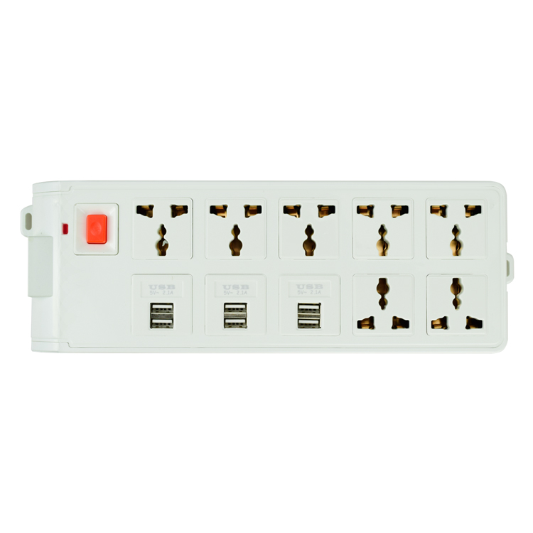
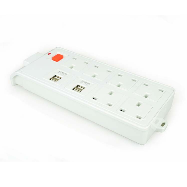
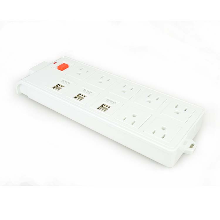
This Multi-way extension lead has lots of practical uses in and around the home, designed for use where you need to connect up to multi-Socket and then feed them from one plug from a mains supply. Very durable and made out of strong materials which makes it suitable for audio visual equipment, computer equipment, telephone equipment, power tools and garden machinery etc. It is widely used for commercial, industrial, hospital and residential purpose.
YIDASHUN has 6 outlet power strip with 4 usb ports, and 7 power sockets with 6 usb ports. Each has a 1.8m long extension lead with switch that can turn off without pluck the socket. And plugs of the power outlet are EU, US, UK and universal plugs for your reference, which is widely used in all countries.


Extension Socket,Power Extension Socket,Switched Extension Socket,Outdoor Extension Socket
Shenzhen Yidashun Technology Co., Ltd. , https://www.ydsadapter.com