With the increase of road speed and the rapid increase of the number of vehicles, the vehicle inspection device must have fast response time, accurate judgment ability and stable working state. Car inspection technology mainly includes: video [1], toroidal coil [2], digital microwave [2], laser and infrared. Although there are many types of detection technologies, there are still many shortcomings: on the one hand, the anti-interference ability is poor, and the product cost is relatively high; on the other hand, the detection response time is long, and it is difficult to detect the high-speed passing vehicle in time and accurately.
For the road environment and vehicle traffic conditions of conventional highways, the vehicle inspection device introduced in this paper adopts the toroidal coil detection technology. The technical principle is simple, the implementation cost is low, and the work is stable and reliable. In terms of signal analysis and processing, the ATmega16A microcontroller with stable performance is used [3]. The vehicle detection signal is directly analyzed and processed by the MCU. The detection response time of each channel is controlled within 2.5 ms. The detection result is indicated by the indicator light on the front panel of the vehicle inspection device, and the RS485 bus is used to send the detection to the host computer or other monitoring equipment. Result packet.
1 System working principle
1.1 Loop coil detection principle
The toroidal coil buried under the road surface is connected to the vehicle inspection device through the feeder, and the LC resonance circuit is formed with the capacitor and the triode on the vehicle inspection device, and the generated sinusoidal oscillation signal is arranged into a square wave signal and sent to the single chip microcomputer. When no vehicle passes, it can be considered that the inductance value formed by the toroidal coil is stable, so the resonant frequency of the LC resonant circuit is also unchanged, and the single-chip microcomputer receives a square wave of a fixed frequency, which is denoted as F1. When there is a passing through the buried toroidal coil, since the motor vehicle is a large metal body, the inductance generated by the buried coil will change, so that the frequency of the LC resonant circuit also changes, and the square wave frequency received by the single chip microcomputer is recorded as F1+ΔF; When the motor vehicle leaves the buried coil, the LC resonance frequency will return to F1, thereby realizing the change of the vehicle's passing frequency to the square wave frequency sent to the single chip microcomputer.
1.2 Working principle of variable counting threshold
For the counting mode using the fixed threshold [4], the main counter is given a fixed time counting time, and the detection signal is used as the counting clock, as shown in FIG. 

2 system functions and their hardware components
This article refers to the address: http://
2.1 Introduction to System Functions
(1) This design uses a variable count threshold detection method. When the MCU is initialized, the upper limit value M of the variable threshold counter is automatically adjusted according to the count value N of the main counter, so that the counting time is within the requirement, and the main counter can also obtain the counting value with a clear discrimination. In fact, it is a balance between detection time and detection sensitivity.
(2) The vehicle inspection device provides two detection channels, each of which can be used alone or in combination. When used alone, it can detect the traffic flow, that is, when the vehicle passes through the toroidal coil, it accumulates the number of vehicles; when used in combination, the vehicle speed can be detected, when the vehicle passes the first coil, the vehicle enters time T1, and when the second coil is entered When the entry time T2 is recorded, the driving speed is V=S/(T2-T1), where S is the separation distance of the two coils.
(3) The vehicle inspection device has the remote control function of the upper computer. The upper computer realizes the working mode of the remote control vehicle and sets the detection parameters (including detection sensitivity, self-tuning, communication baud rate, initialization, channel opening status, etc.) through the RS485 bus. The input and output data format can be framed according to the user's requirements, which improves the applicability of the vehicle.
(4) Parameter setting and working status indication. Two 8-bit DIP switches are used for parameter setting, one of which provides the detection sensitivity and presence time setting of the channel on the front panel, and the other provides address code setting, energy-saving mode, serial port on the board of the vehicle. The setting of functions such as enabling and self-tuning. Eight LEDs are used to indicate the status of the vehicle inspection device on the front panel (including presence indication, fault indication, communication indication, power indication, programming instructions, etc.).
2.2 Hardware components
The hardware component block diagram of the vehicle inspection device is shown in Figure 3, which is described as follows: 
(1) LC resonant circuit: adopts the dual-channel time division multiplexing mode, the external buried toroidal coils are respectively connected to the isolation coils on the vehicle inspection device, and the gating conditions of the two channels are controlled by the single-chip microcomputer, each time only One channel is gated. This not only makes the circuit simpler, but also avoids mutual interference between the two channels.
(2) Controller core circuit: The controller selects ATmega16A-AU, which is a high performance, low power 8-bit AVR microprocessor. It can operate up to 16 MIPS at 16 MHz, only 2 clocks. A periodic hardware multiplier; with 16 KB of in-system programmable Flash and a hardware watchdog. In addition, ATmega16 is able to work stably for a long time in an outdoor open environment, and its price/performance ratio is outstanding. This part is the core circuit of the vehicle inspection device. The variable threshold counter and the main counter use the 8-bit and 16-bit counters integrated in the ATmega16A respectively, which makes the circuit of the whole vehicle detector simpler and has stronger anti-interference ability.
(3) Communication interface module: The external communication of the vehicle inspection device adopts RS485 bus, MAX3485ESA is selected as RS485 differential level conversion chip, and optocoupler device is added for isolation, effectively protecting the internal circuit of the vehicle inspection device from the transmission line. influences. The vehicle inspection device adopts the communication mode of the host inquiry response, and in addition to answering, the other time should maintain the receiving monitoring state, so that the host's inquiry signal can be received in time.
3 software design
The main working process of the MCU is shown in Figure 4. After the car detector is powered on, the MCU initializes the direction and initial level of each I/O port, reads the setting values ​​of each DIP switch on the car detector and initializes each function module, initializes the threshold counter and the main counter, and finally Enable both counters to start counting at the same time. When an external buried coil has an open circuit or a short circuit, the LC resonant circuit will not vibrate, so that the threshold counter does not count the clock; or the LC resonant circuit can start to oscillate, but the frequency is too small due to the aging of the coil or the non-compliance with the standard. In both cases, the main counter count overflows before the threshold counter reaches the upper limit. 
Since the specifications of the ring-buried coils produced by different manufacturers are different, the inductance value can only be in the range of 20 to 1 000 mH. Therefore, it is necessary to adjust the upper limit M of the threshold counter according to the actual inductance of the coil to achieve the optimal count value. To achieve a large count change value within the allowed count time.
The drift compensation of the detection threshold is necessary because in the practical application environment, the resonant frequency of the LC resonance cannot always be stabilized at a value, and the frequency drift is always affected by the environment, and the LC resonance circuit is stabilized even if it is stable. It can only slow down the frequency drift speed.
4 Experimental verification
In order to verify the single-channel detection response time of the vehicle detector, a wide pulse wave is generated from the outside, and the pulse wave is used to simulate the vehicle passing through the buried coil of the vehicle detector, and the waveform shown in FIG. 5 is observed by the oscilloscope (TDS1002). The waveform above is a pulse waveform, and the waveform below is a detection signal (TTL level) output by the vehicle detector after detecting the passage of the vehicle. It can be seen from the displayed waveform that the tester outputs a detection result signal 2.4 ms after the pulse wave is emitted. The experimental results verify that the response time of the vehicle inspection device meets the design requirement of 2.5 ms. 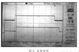
In this paper, the two-channel vehicle detector designed by variable counting threshold method is applied to the detection of information such as driving speed and traffic flow on the road. It has the characteristics of high sensitivity and short detection time. The sample of the vehicle inspection device passed the laboratory test and completed a test within 2.5 ms. The detection sensitivity is satisfactory.
We eliminate tooling costs and save customers money by offering hundreds and hundreds of stock overmolds. For highly customized molded cable manufacturing projects, our advanced technology allows us to produce custom overmolds at a price and quality level that clearly sets us ahead of the competition.
Custom molded wire assembly, overmolded IP67/68 connectors assembling,customized waterproofing cable assembly
ETOP WIREHARNESS LIMITED , https://www.etopwireharness.com