Routing algorithm for UWB ad hoc network based on positioning assistance
1.1 Algorithm design idea The algorithm mainly uses the location information of the node to limit the scope of the route search to a certain interval to reduce the cost of the algorithm, and generates a network topology and routing table based on the location information of the node to complete the routing and forwarding of the packet process. The algorithm consists of three parts: exchange of location information, formation of routing table, routing and packet forwarding, and routing maintenance. In the case of frequent node movement, the position of the node changes frequently, resulting in frequent link disconnection. The algorithm uses the periodically updated distance location exchange packet (DAP) information to obtain the topology information of the network, maintains the local network topology table while obtaining the node position, and calculates the shortest route to other nodes in the entire network according to the topology table. The packet forwarding is first based on the routing information in the local routing table, using the source routing forwarding mode. When the link changes too fast, the speed of the network topology update through DAP cannot keep up with the speed of the link change or other reasons lead to the disconnection of the source route in the packet, the algorithm uses the on-demand method to re-limit based on the existing location information Route discovery in the search range to reduce algorithm overhead. Because the distance information between nodes is obtained using UWB technology, the calculation and control message release required to convert it into position information introduces a certain amount of control overhead.
1.2 Update of network topology and routing table information
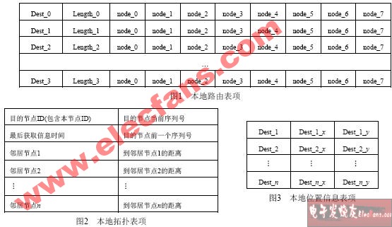
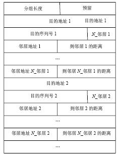
Node location information can be obtained by the method described in [3], including three information tables: local routing table, network topology table and node location information table, as shown in Figure 1, Figure 2 and Figure 3, respectively. Each node periodically broadcasts a truncated table-DAP table containing the distance information set of each node in the network to other neighbor nodes, so as to realize the exchange and update of location information, as shown in FIG. 4. In Figure 4, the packet length is in bytes; "N_neighbor 1" is the number of neighbors of the first destination node; neighbor address N_neighbor 1 is the Nth neighbor node of the first destination node.
The process of periodic active broadcast is as follows: (1) When the network is initialized, nodes continuously exchange information with neighboring nodes to obtain surrounding link state information. After obtaining the topological connection relationship of the nodes of the entire network and the distance between all adjacent nodes, the local routing table is calculated using the minimum distance algorithm. When calculating the coordinates of the global coordinate system of this node, the node with the smallest ID number is the central reference node of the network. (2) The node first increments the destination node sequence number of each item in the topology update information by one, and the node broadcasts the latest distance and topology information known by the node to neighbor nodes. (3) After receiving the DAP information from the one-hop neighbor node, the node updates its local location information table according to the distance information and topology information carried in the packet. If the serial number of the destination node in the DAP information is greater than the serial number of the destination node in the local topology table, the corresponding entry in the DAP information is used to update the corresponding entry in the local topology table; otherwise, it is not updated. After that, the neighbor node broadcasts the latest known network topology connection and node location information to its neighbor nodes. After sufficient information exchange, all nodes can obtain the topological connection of the entire network and the distance between the nodes. Every time the node's local topology table is updated, the local routing table will be recalculated to ensure that the information in the routing table converges to the topology change.
1.3 Routing and packet forwarding
When the node distance information and network topology information are updated regularly, the node uses the local link state information to calculate the routing table to other nodes in the network. Each entry in the routing table stores the entire path information to other nodes. When a node has a packet to send to the destination node, the address information of all transit nodes that reach the destination node in the local routing table is encapsulated in a data packet, and the packet is sent to the next-hop neighbor node by source routing. When the transit node receives the data packet, it first checks whether the address of the next-hop neighbor node encapsulated in the packet is the address of the current node, and if so, records the information of the local node and continues to send the packet to the destination node. When the route from the source node to the destination node is unreachable due to changes in the current network topology or other reasons, the source route maintenance mechanism is used to maintain the route to the destination node.
1.4 Optimization of algorithm by location information
Based on the calculation of the location information of nodes in the entire network, the algorithm uses the location information to limit the transmission range of the request packet to reduce the control overhead. This algorithm only allows intermediate nodes within the allowable forwarding area (request area) defined by the source node to forward routing request packets, reducing the area of ​​routing request packet flooding. The definition of the request area needs to be weighed in two aspects: (1) a smaller request area results in lower routing overhead because a smaller number of nodes are allowed to forward routing request packets; (2) a larger request area will increase the arrival The path of the destination node, especially when the network nodes are sparse. This article uses two request zones, tapered and circular. (1) The cone-shaped request area is defined as a cone-shaped area with the location of the source node as a fixed point, large enough to contain the network area (desired area) to which the routing request packet should arrive. This definition reduces the request area and therefore reduces The cost of route discovery is shown in Figure 5. (2) The circular request area is defined as an area based on distance information. The routing request packet contains the distance dSD between the source node S and the target node D and the location (XD, Y) of the target node. The node I receiving the routing request packet checks whether the condition dDID≤dSD + δ is satisfied. Let dID be the distance between nodes I and D; δ is a given constant, if dID≤dSD + δ, node I will forward the routing request packet; otherwise the packet is discarded. For δ = 0, only nodes that are less than the distance from the target node to the source node are allowed to forward routing packets. The request area is a circular area with (XD, YD) as the center and d as the radius; when δ> 0, the request area increases to a circular area with (XSDD, YD) as the center and dSD + δ as the radius, as shown in Figure 6.

Figure 5 Schematic diagram of the cone-shaped request area Figure 6 Schematic diagram of the circular request area In the route search process, although the location information is used to restrict the desired area of ​​the route, if the route to the destination node is stored in the routing table of the local node, it is not necessary Perform location judgment; only when there is no route to the destination node in the routing table of the local node, the process of on-demand routing maintenance will be initiated. After the transit node receives the request packet, it determines whether the node is located in the desired area. Within the area, the packet request is forwarded. In addition, this algorithm limits route lookup to less than 5 hops, which helps reduce the time for route discovery.
Routing algorithm of ultra-wideband ad hoc network based on location-assisted on-demand topology maintenance
Product application:
â– Products for commercial,household,lighting
Product features:
â– Good heat dissipation
--Blade design of copper alloy contacts,good conductivity
â– Super high impact resistance and thermal stability
--Cover pans are made of high quality polycarbonate
â– Chemical corrosion resistance
-- Corrosion resistant galvanized mounting bracket
â– Grounding.Connection mode
--One-piece grounding design
---Clip in type wiring,spring sheet lock,suitable for #14AWG
hard copper wire
Duplex Receptacle TR UL,White Duplex Receptacle TR UL,Electrical Duplex Receptacle TR UL,Wall Duplex Receptacle TR UL
Hoojet Electric Appliance Co.,Ltd , https://www.hoojetgfci.com